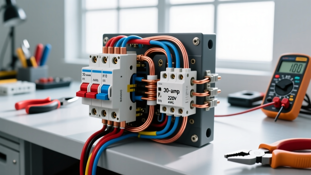
Wiring a meter box—the service entrance enclosure that bridges the utility grid and your home’s electrical panel—is the highest-risk residential electrical task you will encounter. Unlike branch circuits, the line-side lugs of a meter socket have no upstream overcurrent protection. Once the utility drops the service lines, those lugs are live, and the only way to de-energize them is to pull the meter or have the utility disconnect the drop.
Because of this, verifying your work requires a strict, methodical testing sequence. You must perform dead tests before the utility arrives, and live tests after the meter is set. This guide details the exact measurement techniques, probe placements, and expected numerical values to confirm your meter box wiring is safe, code-compliant, and ready for load.
Meter Setup and Safety Category Requirements
Before you touch a single probe to a busbar, you must verify your test equipment is rated for the service entrance. Standard electronics multimeters will catastrophically fail if subjected to a transient voltage spike on the utility grid.
Meter Setup Block for Service Entrance Testing
- Dial Position: V AC (Volts Alternating Current) for live voltage tests; Ω (Ohms) or Continuity for dead tests.
- Lead Jacks: Black lead to COM (Common), Red lead to V/Ω (Voltage/Ohms). Never leave the red lead in the Amps jack when testing voltage.
- Range: Auto-ranging, or manually set to the 600V/1000V AC scale.
- Safety Category: CAT IV 600V minimum. (Refer to Fluke's guide on measurement categories for the physics of transient overvoltages).
- Special Function: Lo-Z (Low Impedance) mode, if available, to eliminate phantom voltage readings on disconnected conductors.
Pre-Energization Verification (Dead Testing)
Before the utility installs the meter, the entire enclosure is dead. This is your only window to verify the physical integrity of your wiring without the hazard of live voltage.
Step 1: Torque and Mechanical Verification
Per NEC 110.14(D), all electrical connections must be tightened to the manufacturer’s specified torque. For a standard 200A meter socket (like a Siemens W0202ML1200), the line and load lugs typically require between 250 and 300 inch-pounds of torque for 2/0 AWG conductors. Use a calibrated torque screwdriver or inch-pound torque wrench. A loose neutral lug here will cause catastrophic overvoltage on 120V circuits once energized.
Step 2: Continuity and Isolation Testing
Set your multimeter to the Continuity or Ohms (Ω) setting.
- Neutral-to-Ground Bond Check: If your meter box is a simple socket feeding a separate main panel, the neutral bus must be isolated from the enclosure. Place one probe on the neutral lug and the other on the bare metal enclosure. Expected reading: OL (Open Line) or infinite resistance. If it reads near 0 Ω, you have an illegal neutral-to-ground bond at the meter socket.
- Load-Side Short Check: With the main breaker in the downstream panel turned OFF, test between the Load L1 and Load L2 lugs. Expected reading: OL. If it reads near 0 Ω, you have a dead short in your service entrance conductors.
Post-Energization Voltage Testing (Live Verification)
Once the utility has installed the meter and energized the service, the line-side lugs are now live at utility voltage. Keep the meter socket cover open (if permitted by your local utility for inspection) and ensure the downstream main breaker is OFF so you are only testing the meter box lugs.
Probe Placement and Expected Readings
Use your CAT IV meter on the V AC setting. Keep one hand in your pocket to prevent current from crossing your chest in the event of a shock.
| Test Point (Red Probe → Black Probe) | Expected Good Value | Bad Value | Probable Cause of Bad Reading |
|---|---|---|---|
| Line L1 → Line L2 | 240V (228V - 252V) | < 220V or > 255V | Utility transformer tap issue; severe voltage drop on utility drop. |
| Line L1 → Neutral Lug | 120V (114V - 126V) | 0V or 240V | Open neutral connection; crossed line/neutral conductors. |
| Line L2 → Neutral Lug | 120V (114V - 126V) | 0V or 240V | Open neutral connection; crossed line/neutral conductors. |
| Neutral Lug → Ground Lug/Enclosure | < 2.0V | > 5.0V | High-resistance grounding electrode; loose neutral bond downstream. |
Note: The acceptable voltage ranges (114V-126V) align with ANSI C84.1 standards for Range A utilization voltage. For deeper code context on service entrance requirements, refer to the NFPA 70 National Electrical Code Article 230.
Mistakes That Cause Misleading Multimeter Readings
When testing a meter box, digital multimeters can sometimes lie to you if you don't understand their internal impedance. Here are the most common measurement traps:
1. Phantom Voltage on Disconnected Conductors
If you are testing a spare, unconnected wire in the meter box conduit, a high-impedance digital multimeter (typically 10 MΩ input impedance) might read 40V to 80V AC. This is phantom voltage caused by capacitive coupling from adjacent live wires in the same conduit. The Fix: Switch your meter to "Lo-Z" (Low Impedance) mode, which drops the input impedance to roughly 3 kΩ, bleeding off the phantom capacitive charge and displaying the true 0V reading.
2. The "Floating Neutral" Illusion
If the utility neutral is broken at the transformer or the weatherhead, testing Line-to-Neutral might yield erratic readings (e.g., 90V on L1 and 150V on L2). Novices often blame the meter box wiring. In reality, the neutral is floating, and the voltage is dividing based on the downstream 120V loads connected to the panel. The Fix: Test Line-to-Ground (the physical metal enclosure or grounding electrode conductor). If Line-to-Ground reads a solid 120V but Line-to-Neutral reads erratically, you have an open utility neutral, not a meter box wiring fault.
3. Using CAT III Meters on the Service Drop
A CAT III 600V meter might successfully read 240V at the meter box under normal conditions. However, if a utility capacitor bank switches or a lightning strike induces a transient spike on the service drop, a CAT III meter lacks the internal arc-gap clearance to safely quench the explosion, posing a severe blast and shrapnel hazard to the user.
Frequently Asked Questions About Wiring a Meter Box
What size wire is typically used when wiring a meter box for a 200A service?
For a standard 200-amp residential service, NEC 310.12(A) allows you to size the service entrance conductors at 83% of the service rating. Therefore, you need conductors rated for at least 166 amps (200A x 0.83). Based on the 75°C column of NEC Table 310.16, this requires 2/0 AWG Copper (rated 175A) or 4/0 AWG Aluminum (rated 180A). Always check the terminal lugs on your specific meter socket; some older or cheaper sockets are only rated for 60°C, which would force you to upsize the wire.
Can I wire a meter box myself without utility approval?
You can physically mount the enclosure and wire the load-side conductors (the feeders going to your main panel) as a licensed electrician or, in some jurisdictions, a homeowner with a permit. However, you cannot wire the line-side (the service drop from the weatherhead to the meter lugs) without utility involvement, nor can you install the meter yourself. The utility must inspect your rough-in, drop their lines, terminate the line-side lugs, install the meter, and apply a security seal. Breaking a utility seal is a criminal offense in most jurisdictions.
Why does my multimeter read 120V on the neutral when wiring a meter box?
If you are measuring between the neutral lug and the earth (or grounding electrode) and reading 120V, you have a critical fault. This almost always indicates an open neutral upstream (either at the utility transformer or the weatherhead splice) combined with a 120V load turned on inside the house. The current is trying to return to the source, backfeeding through your meter box neutral because the primary neutral path is broken. Immediately stop work, keep the main breaker OFF, and contact the utility to check their drop.
How do I test the grounding electrode conductor at the meter box?
The grounding electrode conductor (GEC) connects the meter box or main panel to the ground rods or ufer ground. To verify its integrity without digging, perform a live voltage test between the Line L1 lug and the GEC wire itself (where it lands on the ground bus or enclosure). You should read a solid 120V (within the 114V-126V range). If you read significantly lower (e.g., 80V) or the reading fluctuates wildly when heavy appliances cycle, your grounding electrode system has high resistance and requires physical inspection or additional ground rods.