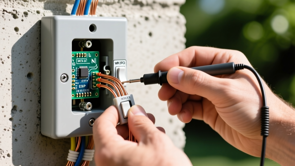
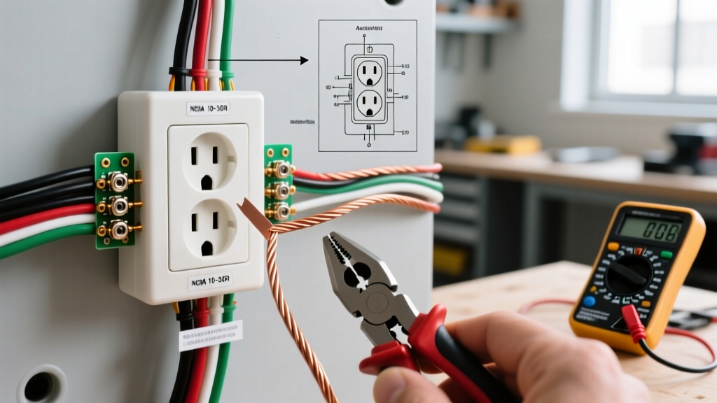
Why Build a Physical Layer Circuit Switch in Computer Networks?
To build a physical circuit switch in computer networks for home lab ISP failover, use a pair of 12V DC DPDT electromechanical relays to physically route the Ethernet TX/RX pairs at Layer 1. While most home users rely on logical dual-WAN routers (Layer 3), logical failover relies on ICMP polling, ARP cache clearing, and link-state reconvergence. This process typically takes 10 to 30 seconds of dropped packets. A physical layer circuit switch drops the electrical connection entirely, forcing the router's PHY (physical layer transceiver) to instantly detect a link-loss and retrain on the backup circuit in under 1 second.
This guide walks through the exact electrical design, T568B color code wiring, and breadboard testing required to build a reliable Layer 1 network transfer switch for 10/100Base-T environments.
Topology & Node Mapping for Dual-WAN Failover
Unlike packet switching, which breaks data into frames and routes them dynamically, a circuit switch establishes a dedicated, continuous electrical path. For a dual-WAN home lab, we map four distinct nodes to control the physical copper paths.
- Node A (Primary ISP): RJ45 breakout from ISP 1 modem.
- Node B (Backup ISP): RJ45 breakout from ISP 2 modem.
- Node C (Edge Router): The WAN port on your pfSense/OPNsense or enterprise router.
- Node D (Control Logic): A 12V DC power supply triggered by a simple toggle switch, UPS dry-contact, or microcontroller GPIO.
We are switching 10/100Base-T (Fast Ethernet), which only requires two twisted pairs: TX (Transmit) and RX (Receive). According to the TIA/EIA-568-B standard, these map to specific pins on the RJ45 connector:
- TX Pair: Pin 1 (White/Orange) and Pin 2 (Orange)
- RX Pair: Pin 3 (White/Green) and Pin 6 (Green)
Note: Gigabit Ethernet (1000Base-T) uses all four pairs bidirectionally. To switch Gigabit, you would need four DPDT relays or a solid-state analog matrix. For this breadboard design, we restrict the circuit to 10/100Base-T to maintain signal integrity and impedance matching.
Component Selection & Design Walkthrough
When designing a circuit switch in computer networks at the physical layer, contact bounce and crosstalk are your primary enemies. We select components specifically to mitigate these issues while maintaining the 100-ohm characteristic impedance of Cat5e/Cat6 cabling.
The Bill of Materials
| Component | Part Number / Spec | Why This Part? |
|---|---|---|
| Relays (x2) | Omron G5V-2 12V DC | DPDT, 288Ω coil, gold-clad bifurcated contacts for low-level signal reliability. |
| Flyback Diodes (x2) | 1N4007 | Clamps inductive voltage spikes when the relay coil de-energizes, protecting control logic. |
| Control Wiring | 22 AWG Stranded Copper | Handles the ~41mA coil draw easily; flexible for breadboard/rack routing. |
| Ethernet Breakouts | RJ45 to Terminal Block adapters | Allows screw-terminal termination without soldering directly to fragile RJ45 pins. |
Wiring the Control Circuit
The Omron G5V-2 coil pulls roughly 41mA at 12V DC. Wire the 1N4007 flyback diode in parallel with the coil, with the cathode (striped end) pointing toward the +12V source. This provides a recirculation path for the collapsing magnetic field. Without this diode, the inductive kickback can generate hundreds of volts, instantly frying the transistor or microcontroller driving Node D.
Behavior Matrix & Failure Mode Contrast
Understanding what breaks at the extremes is critical when deploying physical layer network hardware. Unlike logical routers that can log errors, a physical circuit switch will silently pass destructive electrical states if misconfigured.
| System State | Relay 1 (ISP A) | Relay 2 (ISP B) | Resulting Path | Failure Mode / Extreme |
|---|---|---|---|---|
| Normal (Primary) | De-energized (NC) | De-energized (NC) | ISP A to Router | None. Default safe state. |
| Failover (Backup) | Energized (NO) | Energized (NO) | ISP B to Router | ISP A link drops instantly. |
| Control Power Loss | Fails to NC | Fails to NC | Defaults to ISP A | Loss of failover capability. |
| Contact Weld (Short) | Welded Closed | Welded Closed | Bus Contention | CRITICAL: Both ISP PHYs drive TX simultaneously. Magic smoke; destroyed NICs. |
Why this topology over the alternative? If you wire the relays in a 'make-before-break' configuration, you risk the bus contention failure mode shown above, where both modems transmit onto the same copper pair simultaneously. We strictly use 'break-before-make' DPDT relays to ensure a microsecond open-circuit gap during transition, protecting the transformer magnetics inside the RJ45 jacks.
Decision Tree: Electromechanical vs. Solid-State vs. Logical
Not every homelab needs a physical layer switch. Use this decision matrix to determine if a hardware circuit switch is the right tool, or if you should fall back to software routing.
| Condition / Requirement | Recommended Architecture | Concrete Pick |
|---|---|---|
| Need Gigabit (1000Base-T) speeds? | Logical Dual-WAN Router or Solid-State Matrix | MikroTik RB5009 or ADG1414 IC |
| Need sub-1s failover for 10/100 IoT networks? | Electromechanical Layer 1 Circuit Switch | Omron G5V-2 (Default Pick) |
| Require PoE pass-through on WAN link? | Logical Router (Do not use physical relays) | Ubiquiti EdgeRouter with PoE |
| Budget is under $15, low speed acceptable? | Electromechanical Layer 1 Circuit Switch | Omron G5V-2 on breadboard |
The Default Recommendation: For isolated 10/100Base-T management networks, IPMI interfaces, or legacy VoIP PBX uplinks where a 30-second logical reconvergence is unacceptable, the Omron G5V-2 electromechanical relay is the definitive choice. It provides a true physical air-gap break, costs under $3 per unit, and handles the low-voltage differential signaling (LVDS) of Fast Ethernet without introducing fatal crosstalk.
Step-by-Step Breadboard Test Sequence
Before wiring this into your production network rack, validate the switching logic and contact integrity on a breadboard. Refer to the All About Circuits relay guide for foundational electromechanical theory if you are new to coil-driven switching.
- Verify Coil Integrity: Set your multimeter to resistance (Ω). Probe pins 2 and 9 on the Omron G5V-2. You should read exactly 288Ω (±10%). If it reads infinite, the internal coil is severed; discard the relay.
- Install Flyback Protection: Insert the relay into the breadboard. Place the 1N4007 diode across the coil pins. The silver cathode stripe must face the +12V rail. Reversing this will create a dead short across your power supply when the relay energizes.
- Map the NC/NO Continuity: With the relay de-energized, set your DMM to continuity mode. Probe Pin 1 (Common) and Pin 4 (NC). You should hear a beep. Probe Pin 1 and Pin 12 (NO). It must remain open. This confirms your T568B default path.
- Energize and Verify Shift: Apply 12V DC to the coil circuit. You will hear an audible click. Immediately re-test continuity. Pin 1 to Pin 4 must now be open. Pin 1 to Pin 12 must now beep. The physical air-gap has shifted the circuit.
- Measure Contact Resistance: While energized, switch your DMM to measure milliohms (mΩ) across the closed NO contacts. A healthy gold-clad Omron relay will read under 50mΩ. If you read >1Ω, the contacts are oxidized or pitted, which will attenuate your Ethernet signal and cause packet loss.
- Live Network Validation: Connect Node A to a 10/100 switch port and Node C to a laptop. Verify link lights illuminate and you can ping the gateway. Trigger the 12V control circuit. The laptop link light should extinguish for roughly 50 milliseconds, then illuminate on the Node B backup path.
By treating the network link as a raw electrical circuit rather than a stream of IP packets, you bypass the software stack entirely. This physical circuit switch design guarantees that when your primary ISP drops, your edge router reacts at the speed of electricity, not the speed of a routing protocol.