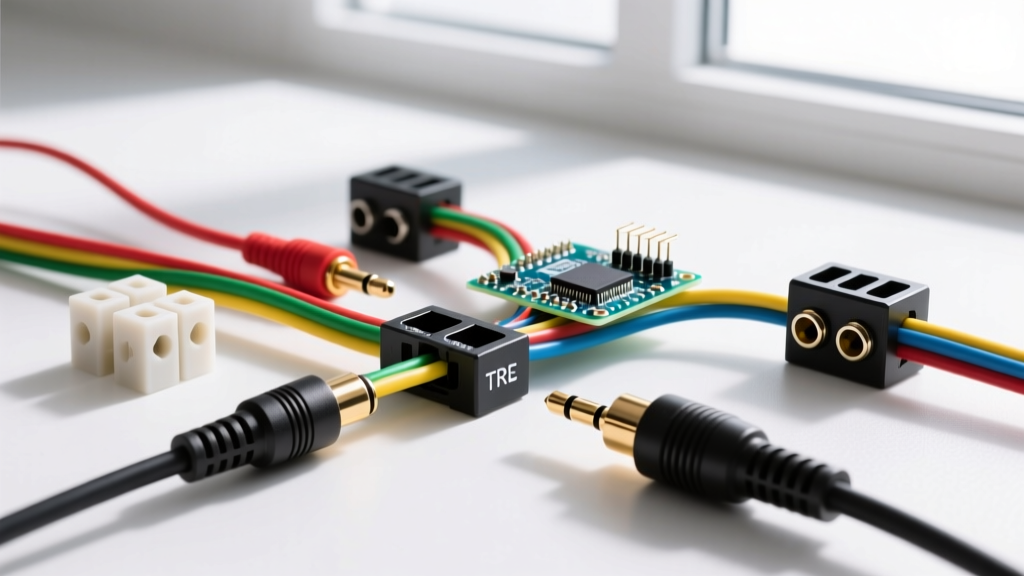

A standard headphone socket pinout maps low-voltage audio signals to physical contacts. For a 3-pole TRS (Tip, Ring, Sleeve) jack, the pinout is Tip (Left Audio), Ring (Right Audio), and Sleeve (Ground). For a 4-pole TRRS jack, the standard CTIA pinout adds a second Ring for the Microphone. Standard internal wire colors are White or Black (Left), Red (Right), Bare/Copper (Ground), and Green or Yellow (Mic). Below is the master reference table for bench wiring and repair.
The Master Headphone Socket Pinout & Color Code Table
Use this table when terminating 3.5mm (1/8') or 6.35mm (1/4') audio cables to panel-mount jacks like the CUI Devices SJ-series or Switchcraft 35RAPC. Always verify your specific manufacturer's datasheet, as switching jacks include extra detection pins.
| Pin / Contact | TRS (3-Pole) Function | TRRS CTIA (4-Pole) Function | TRRS OMTP (4-Pole) Function | Standard Wire Color |
|---|---|---|---|---|
| Tip (T) | Left Audio | Left Audio | Left Audio | White or Black |
| Ring 1 (R1) | Right Audio | Right Audio | Right Audio | Red |
| Ring 2 (R2) | N/A | Ground (Common) | Microphone | Bare / Copper (CTIA) or Green (OMTP) |
| Sleeve (S) | Ground (Common) | Microphone | Ground (Common) | Bare / Copper (OMTP) or Green (CTIA) |
| Pin 4 (Switch) | Normally Closed (NC) to Tip | NC to Tip (Detection) | NC to Tip (Detection) | N/A (Internal PCB trace) |
| Pin 5 (Switch) | Normally Closed (NC) to Ring | NC to Ring (Detection) | NC to Ring (Detection) | N/A (Internal PCB trace) |
Standard Variants: IEC, CTIA, OMTP, and Legacy UK
When readers ask about 'NEC vs IEC vs old UK' standards in the context of audio jacks, it is critical to separate mains electrical code from low-voltage signal standards. Audio jacks do not carry lethal voltage, so their physical and electrical mappings are governed by telecommunications and electronics bodies, not high-voltage wiring codes.
NEC Article 725 (Wiring Method, Not Pinout)
The National Electrical Code (NEC) does not define headphone pinouts. Instead, NEC Article 725 classifies audio and headphone wiring as Class 2 or Class 3 remote-control and signaling circuits. This means the wiring is exempt from standard 120V mains requirements (you do not need THHN in conduit or NM-B Romex). Standard 24AWG to 28AWG stranded copper with PVC or TPE insulation is code-compliant for in-wall audio runs, provided it carries the appropriate CL2 or CL3 rating for fire safety.
IEC 60603 vs CTIA vs OMTP
The International Electrotechnical Commission (IEC) standard 60603-11 governs the physical dimensions and mechanical tolerances of 3.5mm and 6.35mm connectors globally. However, the electrical pinout for 4-pole (TRRS) headsets is split between two competing standards:
- CTIA (AHJ): The modern global standard (used by Apple, Samsung, and most modern PC audio). Pinout is Tip (L), Ring1 (R), Ring2 (GND), Sleeve (Mic).
- OMTP: An older standard (used by early Nokia, Sony Ericsson, and some legacy Samsung devices). Pinout is Tip (L), Ring1 (R), Ring2 (Mic), Sleeve (GND). Plugging a CTIA headset into an OMTP jack results in muffled audio and a non-functional microphone because the ground and mic pins are swapped.
The Old UK B-Gauge and Domino Sockets
Before the 3.5mm TRS jack became universal, the UK utilized the B-gauge (PO 316) and the 3-pin 'domino' socket (BS 6318) for telecommunications and early audio equipment. These legacy sockets featured entirely different physical diameters and wired the Tip, Ring, and Sleeve to unbalanced audio and signaling grounds differently. If you are restoring vintage UK audio gear, do not assume modern 3.5mm TRS color codes apply; trace the circuit back to the output transformer or amplifier stage.
Pins and Rows People Get Wrong
Even experienced makers make specific errors when wiring panel-mount headphone jacks. Here are the most common pitfalls and how to avoid them.
A standard PCB-mount TRS jack like the CUI Devices SJ-3524 has 5 pins, not 3. Pins 1, 2, and 3 are Tip, Ring, and Sleeve. Pins 4 and 5 are Normally Closed (NC) mechanical switches. When no plug is inserted, Pin 4 is shorted to Tip, and Pin 5 is shorted to Ring. Inserting a plug breaks these connections to signal the host device. If you accidentally solder your audio lines to Pins 4 and 5, your audio will cut out the moment you plug in your headphones.
Mistake 1: Swapping Ground and Mic on TRRS
Because CTIA and OMTP swap the Sleeve and Ring 2 connections, buying a replacement TRRS cable without verifying the host device's standard will result in a 'hollow' vocal sound. The audio signals are out of phase because the ground reference is floating through the microphone bias voltage. The Fix: If you cannot determine the standard, wire the jack for CTIA (the modern default) and use an inline CTIA-to-OMTP adapter (costing roughly $5) if the device requires the legacy standard.
Mistake 2: Safe Interpretation When Markings Fade
On salvaged or heavily used PCBs, the silkscreen markings for T, R, S, and GND often fade or are obscured by flux residue. Never guess the pinout based on physical proximity.
Bench Procedure for Faded Markings:
1. De-energize the device and disconnect the battery.
2. Set your multimeter to the continuity/diode test mode.
3. Insert a known-good 3.5mm TRS plug into the socket.
4. Probe the exposed Tip, Ring, and Sleeve of the plug with one lead, and probe the PCB traces with the other.
5. The trace that shows < 1 ohm of resistance to the plug's Tip is your Left Audio; the Ring is Right Audio; the wide Sleeve barrel is Ground. Mark them immediately with a paint pen.
Headphone Socket Pinout FAQ
How do I wire a 4-pole TRRS headphone socket pinout for a custom cable?
To wire a custom 4-pole TRRS cable, strip the outer jacket to reveal the four internal conductors. Using the CTIA standard, solder the White/Black wire to the Tip pin (Left), the Red wire to Ring 1 (Right), the Bare/Copper wire to Ring 2 (Ground), and the Green/Yellow wire to the Sleeve pin (Microphone). Use a low-temperature soldering iron (around 300°C / 570°F) and apply flux to the tiny pins to prevent thermal damage to the plastic housing of the jack. Always use heat shrink tubing over each solder joint to prevent the fine stranded wires from bridging and causing a short.
Why does my headset microphone not work even if the headphone socket pinout matches?
If your pinout is correct but the microphone fails, the issue is usually related to DC bias voltage (Plug-in Power). Most modern PC and smartphone audio jacks supply a 2V to 3V DC bias on the Microphone pin to power electret condenser microphones. If you are wiring a dynamic microphone (which requires no power) or a line-level signal into a TRRS jack expecting an electret mic, the impedance mismatch and DC bias will prevent proper operation. You must use a DC-blocking capacitor (typically 1µF to 10µF) in series with the microphone pin to protect your audio source and match the expected impedance.
What is the difference between a 3-pin and 5-pin panel mount headphone jack?
A 3-pin panel mount jack provides only the basic audio connections: Tip, Ring, and Sleeve. A 5-pin (or sometimes 6-pin) panel mount jack includes integrated mechanical isolation switches. These extra pins are used by the host device's microcontroller to detect when a plug is physically inserted, allowing the device to automatically mute internal speakers and route audio to the headphones. If you are replacing a broken 5-pin jack with a 3-pin jack in a DIY repair, the audio will work, but the device will not automatically detect the headphones, and you will need to manually switch the audio output in the software settings.


