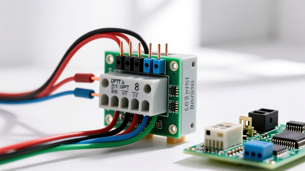
If your light switch glows when off, you are dealing with one of two scenarios: a built-in locator light functioning exactly as designed, or a 'ghost voltage' issue caused by a missing neutral wire or swapped Line/Load connections. When upgrading to smart switches (like the Leviton Decora Smart DW15S or Lutron Caséta) or illuminated mechanical toggles, failing to connect the neutral wire or misidentifying the Line and Load conductors will cause the switch's internal LED indicator to glow dimly when the light is ON, or cause your LED bulbs to flicker and glow when the switch is OFF.
The direct fix is to properly pigtail the switch's white neutral lead to the neutral bundle in the back of the box, and strictly terminate the source black wire to the LINE terminal and the fixture black wire to the LOAD terminal. Below is the exact wiring procedure, device specifications, and testing protocol to eliminate the glow and ensure a code-compliant installation.
Switch Types and the Physics of the 'Ghost Glow'
Before stripping wires, you must understand why the glow happens. Modern LED bulbs draw incredibly low current (often under 0.1A). When a smart switch is installed without a neutral wire, it attempts to power its internal Wi-Fi or radio electronics by trickling a tiny leakage current (usually under 1mA) through the load (the LED bulb) and back to the panel via the fixture's neutral. This micro-current charges the bulb's internal capacitor, resulting in a faint glow or a rhythmic strobe effect when the switch is off. Providing a dedicated neutral wire at the switch box gives the switch's electronics a direct return path to the panel, bypassing the LED bulb entirely.
The table below breaks down the exact behavior, neutral requirements, and wire gauges for the most common switch types you will encounter on a 15-amp residential lighting circuit.
| Switch Type & Example Model | Neutral Required? | Indicator Glows When... | Common 'Ghost Glow' Cause | Wire Gauge (15A Circuit) |
|---|---|---|---|---|
| Standard Mechanical Toggle (e.g., Leviton 1451) | No | Never | N/A | 14 AWG Copper |
| Illuminated Locator (e.g., Leviton 5611) | No | OFF (to locate in dark) | Line/Load swapped (glows when ON) | 14 AWG Copper |
| Smart Switch w/o Neutral (e.g., Lutron PD-6WCL) | No | ON (status indicator) | Incompatible LED driver (bulb glows) | 14 AWG Copper |
| Smart Switch w/ Neutral (e.g., Leviton DW15S) | Yes (NEC 404.2) | ON (status indicator) | Disconnected or missing neutral wire | 14 AWG Copper |
Tools & Materials for a Code-Compliant Install
Do not rely on twist-on wire connectors for smart switch neutrals; the solid-to-stranded connections often work loose when pushing the bulky switch body back into the box. Use the following specific materials for a reliable, high-density termination.
- Switch: Leviton Decora Smart Wi-Fi 15A Switch (DW15S) or equivalent 15A/120V rated neutral-requiring smart switch.
- Wire: 14 AWG THHN stranded copper wire (white for neutral pigtails, black for Line/Load pigtails if needed). Note: If your home has 12 AWG wire on a 20A breaker, you must use a 20A-rated switch and 12 AWG pigtails.
- Connectors: Wago 221 3-port lever nuts (rated 20A/600V) for secure neutral pigtailing.
- Voltage Tester: Klein Tools NCVT-3 non-contact voltage tester (CAT IV 1000V rated).
- Multimeter: Fluke 117 True-RMS Multimeter with LoZ (Low Impedance) mode to prevent false ghost voltage readings on the meter itself.
- Strippers: Klein Tools 11055 wire strippers (calibrated for 14-10 AWG solid/stranded).
- Screwdriver: Klein Tools 32500 multi-bit screwdriver with a #2 Phillips and 1/4-inch flathead.
Mains Safety & Preparation Protocol
Working inside a switch box exposes you to 120V AC mains voltage, which can cause fatal electrocution or severe arc flash burns. You must de-energize the circuit at the main breaker panel before removing the wallplate. Turn off the specific 15A or 20A breaker controlling the light. Apply a lockout/tagout device, or place a piece of heavy electrical tape over the breaker handle to prevent accidental re-energization. Always verify the circuit is dead using the Live-Dead-Live test method outlined in the testing section below. NEC-style guidance is provided here; your local Authority Having Jurisdiction (AHJ) has final authority on code compliance and may require a licensed electrician for this work.
Once the breaker is off and the wallplate is removed, pull the switch out of the box by unscrewing the top and bottom mounting ears. Do not touch any bare wire ends until you have verified the absence of voltage. Take a clear photo of the existing wiring before disconnecting anything. In older homes, you may not find a neutral bundle (white wires) in the switch box. According to NEC Article 404.2(C), new installations and major renovations require a grounded (neutral) conductor at the switch box to accommodate smart switches. If your box lacks a neutral, you must either use a no-neutral smart switch (like the Lutron Caséta PD-6WCL with a Lutron Pico remote) or hire an electrician to pull a new 14/3 or 14/2 NM-B cable from the fixture to the switch box.
Step-by-Step Wiring: Terminating Line, Load, Neutral, and Ground
Assuming you have a verified neutral bundle in the back of the box and are installing a 15A neutral-requiring smart switch (like the Leviton DW15S), follow these exact termination steps. Ensure you strip exactly 5/8-inch of insulation from your 14 AWG wires for proper terminal insertion.
- Identify and Separate Conductors: Locate the Line wire (always hot, usually black, coming from the breaker), the Load wire (usually black or red, going up to the light fixture), the Ground bundle (bare copper or green), and the Neutral bundle (white wires joined together in the back of the box).
- Pigtail the Neutral: Open the white neutral bundle. Do not disconnect the existing neutrals. Add a 6-inch length of 14 AWG white THHN stranded wire to the bundle using a Wago 221 3-port lever nut. This pigtail will connect to your switch.
- Terminate the Ground: Take the bare copper or green grounding wire from the switch and loop it clockwise around the green grounding screw at the bottom of the switch yoke. Tighten the screw to 14 in-lbs. Push the bare ground wires neatly into the deepest part of the back of the box to save space for the switch body.
- Terminate the Line (Source):strong> Connect the black Line wire (the one that tested hot before you turned off the breaker) to the switch's black 'LINE' terminal. If your switch uses screw terminals, loop the wire clockwise; if it uses push-in backwire clamps, insert the straight stripped end until the brass clamp bites the copper.
- Terminate the Load (Fixture): Connect the black or red Load wire (the one going to the light fixture) to the switch's red 'LOAD' terminal. Do not swap this with the Line terminal.
- Terminate the Neutral: Connect the 14 AWG white neutral pigtail you created in Step 2 to the switch's white 'NEUTRAL' terminal or white lead wire using a Wago 221 lever nut. This completes the 120V circuit for the switch's internal electronics.
- Mount and Dress: Carefully fold the wires in a Z-pattern (ground first, then neutral, then Line/Load) and push the switch into the box. Secure it with the provided mounting screws, ensuring the yoke sits flush against the drywall without bowing.
Verify & Test: Meter Readings and the 'Botch' Check
Before installing the wallplate and pairing the switch to your app, you must verify the wiring is correct. Remove the tape from the breaker and turn the circuit back on.
The Live-Dead-Live Verification
If you are testing before turning the breaker back on, use your Klein NCVT-3 on a known live outlet first (Live), then test the switch box wires to ensure they are off (Dead), then test the known outlet again to ensure the tester battery hasn't died (Live). Once the breaker is ON for the new switch, use your Fluke 117 multimeter set to AC Voltage (V~).
- Line to Neutral: Place the black probe on the black Line wire and the red probe on the white Neutral pigtail. Expected reading: 114V to 126V AC. This confirms the switch's internal radio is receiving clean power.
- Load to Neutral (Switch OFF): Place the black probe on the red Load terminal and the red probe on the white Neutral. Expected reading: 0V AC (or < 2V ghost voltage, which the Fluke's LoZ mode will filter out). If you read 120V here when the switch is off, the switch's internal triac has failed short.
- Load to Neutral (Switch ON): Turn the switch on. Expected reading: 114V to 126V AC. This confirms power is reaching the fixture.
The Most Common Botch: Swapping Line and Load
The single most frequent mistake DIYers make when installing smart or illuminated switches is swapping the Line (source) and Load (fixture) wires. Because a standard mechanical toggle switch simply bridges two brass screws, it doesn't matter which black wire goes to which screw. Smart switches and illuminated locator switches, however, contain internal microprocessors that require a specific 120V reference from the Line side.
Symptom of the Botch: If you wire the fixture wire to the LINE terminal and the source wire to the LOAD terminal, the switch's internal electronics will attempt to draw power backward through the LED bulb. The result? The switch's indicator LED will glow dimly when the light is ON, and turn off when the light is OFF (the exact opposite of normal behavior). Furthermore, smart switches wired backward will constantly reboot, fail to connect to Wi-Fi, or display a flashing red error LED because the voltage drops below the 90V brownout threshold every time the internal radio transmits.
The Fix: Turn the breaker back off. Pull the switch out, identify the true Line wire (the one that is hot when the wires are separated and the breaker is on), and swap the wires on the black LINE and red LOAD terminals. According to the Lutron Caséta Advanced Installation Guide, misidentifying Line and Load is the leading cause of support calls for smart lighting installations. Always use a non-contact voltage tester to identify the Line wire before you disconnect the old switch.