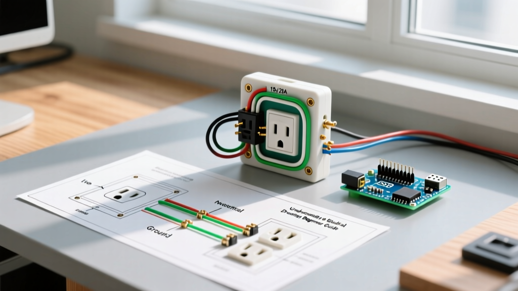

Understanding the Duplex Receptacle Anatomy
When electricians and advanced DIYers search for a wiring diagram for double outlet configurations, they are referring to the standard NEMA 5-15R or 5-20R duplex receptacle. This single device features two plug sockets mounted on a single yoke (strap). In 2026, the market standard for residential 15A applications remains the Leviton 5320-W or the Hubbell 5262, typically costing between $1.50 and $3.00 for residential grade, and up to $7.50 for commercial spec-grade models.
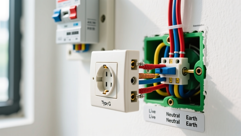
Before consulting any schematic, you must understand the terminal layout:
- Brass Terminals (Hot): Connect to the black (or red) ungrounded conductor.
- Silver Terminals (Neutral): Connect to the white or gray grounded conductor.
- Green Terminal (Ground): Connect to the bare copper or green equipment grounding conductor (EGC).
- Break-Off Fins: Located on the brass and silver sides, these allow you to isolate the top and bottom receptacles for specialized circuits.
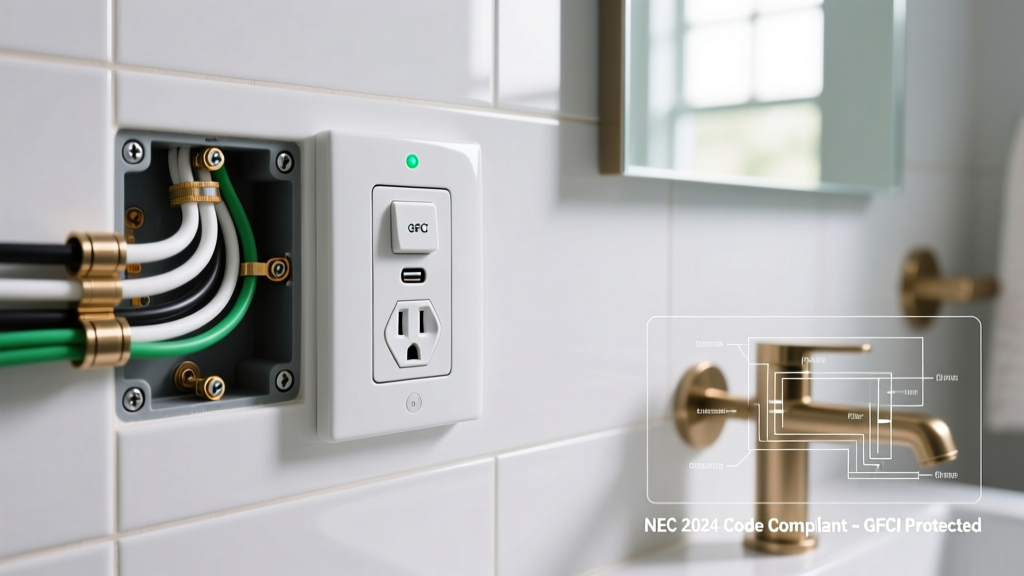
NEC Code Warning: According to the NFPA 70 National Electrical Code, all 15A and 20A, 125V duplex receptacles installed in dwelling unit kitchens, bathrooms, garages, and outdoor areas must be GFCI protected (NEC 210.8). Furthermore, AFCI protection is mandated for almost all living spaces (NEC 210.12). Always verify local amendments before pulling wire.
Core Wiring Diagrams for Double Outlets
There are three primary ways to wire a duplex receptacle, depending on the circuit topology and the desired functionality of the top and bottom sockets.
Configuration 1: Standard Series (Daisy Chain) Wiring
In a series or 'daisy chain' configuration, the power enters the first set of terminals (Line) and exits through the second set (Load) to feed downstream outlets. The internal brass and silver bus bars bridge the top and bottom sockets.
- Hot (Black): Incoming black to top brass screw; outgoing black to bottom brass screw.
- Neutral (White): Incoming white to top silver screw; outgoing white to bottom silver screw.
- Ground (Bare): Incoming and outgoing grounds twisted together and pigtailed to the green screw.
Expert Insight: While common in older homes, series wiring is vulnerable. If a wire nut fails or a terminal loosens at this receptacle, all downstream outlets lose power. Furthermore, pushing two wires under a single terminal screw is a severe NEC violation.
Configuration 2: Parallel (Pigtail) Wiring
Parallel wiring using pigtails is the modern gold standard for residential and commercial construction. Instead of using the receptacle's internal bus bars to pass current downstream, you connect all incoming and outgoing wires together using wire nuts or lever connectors (like Wago 221 series), adding a short 6-inch 'pigtail' wire to connect to the receptacle.
- Hot Pigtailing: Splice incoming black, outgoing black, and a 6-inch black pigtail. Attach the pigtail to the brass screw.
- Neutral Pigtailing: Splice incoming white, outgoing white, and a 6-inch white pigtail. Attach to the silver screw.
- Code Compliance: NEC 300.13(B) strictly requires neutral pigtailing on Multiwire Branch Circuits (MWBC) so that removing the receptacle does not break the neutral path for the other phase.
Configuration 3: Split-Wired (Half-Hot / Switched) Outlet
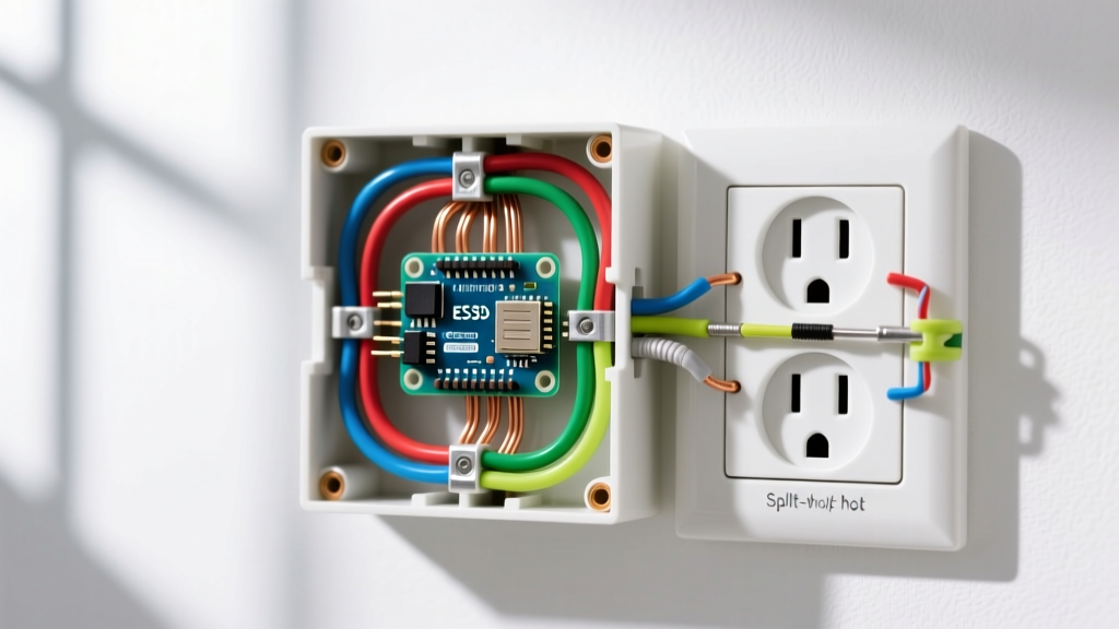
A split-wired diagram isolates the top and bottom sockets. This is commonly used in living rooms where the top plug is controlled by a wall switch (for lamps) and the bottom plug remains always-on for vacuums or routers.
- Use needle-nose pliers to snap off the brass break-off fin on the side of the receptacle. Leave the silver fin intact to share the neutral.
- Connect the always-on hot (usually black) to the bottom brass terminal.
- Connect the switched hot (usually red) from the wall switch to the top brass terminal.
- Connect the shared neutral to either silver terminal.
Comparison Matrix: Series vs. Parallel vs. Split
| Configuration | Primary Use Case | Reliability | Material Cost Adder | NEC Code Nuance |
|---|---|---|---|---|
| Series (Daisy Chain) | Basic lighting circuits, low-draw bedroom outlets | Moderate (Downstream vulnerability) | $0.00 (Uses device terminals) | Prohibited for neutrals on MWBCs |
| Parallel (Pigtail) | Kitchens, bathrooms, commercial spec-grade builds | High (Independent downstream feed) | ~$0.25 per box (Wire + Wago 221) | Mandatory for MWBC neutrals (300.13(B)) |
| Split-Wired | Living rooms, bedrooms (switched lamps) | High (Isolated hot paths) | ~$0.15 (Requires 3-wire Romex/BX) | Requires handle-tied breakers if fed by MWBC |
Step-by-Step Execution: Wiring a Parallel Duplex Receptacle
Follow this precise procedure to ensure a safe, code-compliant installation that will pass municipal inspection and prevent thermal failures.
- Verify De-energization: Use a non-contact voltage tester, followed by a digital multimeter (e.g., Fluke T6-1000) measuring Line-to-Neutral and Line-to-Ground to confirm 0.0V.
- Strip the Wires: Use the 12 AWG or 14 AWG gauge hole on your wire strippers. The strip length should be exactly 5/8-inch to 3/4-inch. Most modern Leviton and Eaton receptacles feature a physical strip gauge molded into the back of the yoke.
- Create the Pigtails: Cut 6-inch lengths of 12 AWG or 14 AWG THHN/THWN wire (matching the circuit gauge). Strip both ends.
- Make the Splices: Combine the circuit wires and the pigtail. If using wire nuts (like Ideal 341 Yellow), twist the wires clockwise and thread the nut until tight. Tug-test each wire. If using Wago 221 lever nuts, simply strip 11mm, lift the lever, insert, and clamp.
- Form the Terminal Hooks: Using needle-nose pliers, bend the stripped end of the pigtail into a 'J' hook. The hook must curve clockwise. This ensures that tightening the terminal screw pulls the hook closed rather than pushing it out.
- Torque to Specification: Hand-tighten the screw, then use a torque screwdriver set to the manufacturer's specification. For most 15A/20A duplex receptacles, this is 14 in-lbs. Under-torquing causes arcing; over-torquing strips the brass threads.
- Wrap or Push? Modern code does not require electrical tape over the terminal screws, provided the box is properly grounded and the drywall fits snugly. Tape can actually trap heat and hide loose connections during future inspections.
Troubleshooting Common Double Outlet Failures
When a duplex receptacle fails, it is rarely the internal copper bus bar that breaks. According to data analyzed by the U.S. Consumer Product Safety Commission (CPSC), the vast majority of residential electrical fires originate at poor connections. Look for these specific failure modes:
- Backstab (Push-In) Failures: Builder-grade receptacles often feature spring-loaded push-in terminals on the back. Over time, the thermal cycling of high-draw appliances (like space heaters pulling 12.5A) causes the internal spring to lose tension. This creates high resistance, melting the plastic yoke. Solution: Always side-wire using the terminal screws, or buy 'spec-grade' receptacles with screw-clamp back-wiring (e.g., Hubbell 5362).
- Shared Neutral Overload: In older split-wired setups, if the two hot legs (Black and Red) are accidentally placed on the same phase (e.g., both on Phase A instead of Phase A and Phase B), the shared neutral will carry the sum of both loads instead of the difference, leading to a melted neutral wire and severe fire hazard.
- Loose Drywall Clamping: If the receptacle wiggles when you plug in a device, the yoke can flex, slowly backing out the terminal screws over months of use. Use plastic receptacle shims (cat. no. SHIM-1) behind the mounting ears to create a rigid, flush fit against the drywall.
Expert FAQ
Can I wire a 20A double outlet with 14 AWG wire?
No. A 20A receptacle (NEMA 5-20R, identifiable by the T-shaped neutral slot) requires a minimum of 12 AWG copper wire protected by a 20A breaker. Installing 14 AWG wire on a 20A circuit is a direct violation of NEC 240.4(D) and creates a severe overheating hazard.
Do I need to ground both the metal box and the receptacle?
Yes. If you are working in a metal junction box, the bare copper ground wire must first be bonded to the back of the metal box using a green 10-32 grounding screw. A separate ground pigtail must then be run from the box (or the main splice) to the green screw on the duplex receptacle. The OSHA Electrical Safety Guidelines emphasize that redundant grounding paths are critical for clearing faults in commercial environments.
Why does my split-wired outlet trip the GFCI breaker immediately?
This almost always happens when an electrician breaks off the silver (neutral) fin but forgets to break off the brass (hot) fin, or vice versa, on a GFCI-protected multiwire branch circuit. GFCI devices measure the exact current differential between the hot and neutral. If a split-wired receptacle shares a neutral but draws from two separate GFCI breakers, the differential will be unbalanced, causing an immediate trip. Split-wired outlets cannot be downstream of standard GFCI receptacles; they require a specialized 2-pole GFCI breaker.