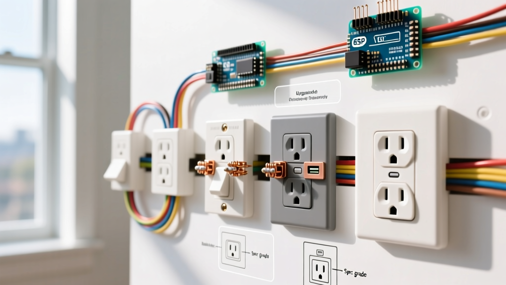
A basic light switch wiring diagram for a single-pole switch routes the ungrounded (hot) conductor through the switch to interrupt power to the load, while the grounded (neutral) conductor bypasses the switch and runs directly to the fixture. If you are wiring a standard 120V, 15-amp lighting circuit using 14/2 NM-B cable, the physical switch only breaks the hot leg. The neutral completes the circuit back to the panel without ever touching the switch terminals.
Decoding the Basic Light Switch Wiring Diagram Symbols
Before tracing the physical wires, you must understand the schematic symbols used in standard NEC-style electrical drawings. A basic single-pole diagram relies on four primary symbols:
- Circuit Breaker: Represented by a square or rectangle on the main bus line, often labeled with its ampacity (e.g., 15A). This is your overcurrent protective device (OCPD).
- Single-Pole Switch (SPST): Drawn as a break in the line with a hinged lever (a line with an open gap and a diagonal strike). This represents the physical mechanical interrupt.
- Load (Light Fixture): Typically a circle with an 'X' through it, or a specific luminaire symbol. This is the impedance where electrical energy converts to light and heat.
- Wire Nut / Splice: A solid dot where two lines intersect, often enclosed in a small circle. This indicates a physical connection (like a wire nut or Wago lever) rather than just wires crossing.
Node-by-Node Trace: From Panel to Fixture
To wire this correctly, follow the current path from the source to the load. This trace assumes a standard 15A branch circuit using 14/2 NM-B (Romex) cable with a black (hot), white (neutral), and bare (ground) conductor.
Step 1: Panel to Switch Box (The Source)
Power originates at the 15A single-pole breaker. The black (hot) wire carries 120V AC nominal (acceptable range 114V–126V) to the switch box. The white (neutral) and bare (ground) wires travel alongside it in the same NM-B jacket.
Step 2: Inside the Switch Box (The Interruption)
This is where the diagram's logic physically manifests.
- The Hot Path: The incoming black wire connects to one of the brass terminal screws on the single-pole switch.
- The Neutral Bypass: The incoming white neutral wire does not connect to the switch. It passes straight through the box, splicing via a wire nut to the outgoing white wire heading to the light fixture.
- The Switched Hot: A second black wire (or a red wire, if using 14/3 for clarity) connects to the second brass screw on the switch and runs up to the fixture.
Step 3: Switch Box to Fixture (The Load)
At the ceiling box, the switched hot (black/red) connects to the black fixture wire. The bypassed neutral (white) connects to the white fixture wire. When the switch lever is toggled, it bridges the two brass terminals, completing the 120V potential across the fixture's ballast or LED driver.
Physical Device Terminal Mapping and Verification
Standard single-pole switches (like the Leviton 1451 or Eaton 1451) are mechanically simple. Unlike 3-way switches or smart switches, standard single-pole toggles are non-polarized regarding the two line/load brass screws. However, knowing exactly what each screw does is critical for troubleshooting.
| Physical Terminal | Screw Color | Electrical Function | Connected Wire (14/2 NM-B) |
|---|---|---|---|
| Terminal 1 | Brass | Line (Hot In) OR Load (Switched Hot Out) | Black (Incoming Hot) |
| Terminal 2 | Brass | Load (Switched Hot Out) OR Line (Hot In) | Black or Red (Outgoing to Fixture) |
| Ground Screw | Green | Equipment Grounding Conductor (EGC) | Bare Copper (Pigtail) |
How to Verify Each Connection with a Meter
Never assume a circuit is wired correctly just because the light turns on. Use a digital multimeter (like a Fluke 117) to verify the integrity of your basic light switch wiring diagram.
- De-energized Continuity Test (Ohms Ω): With the breaker OFF and wires disconnected, set your meter to continuity. Touch one probe to the incoming black wire and the other to the switch's brass screw. Toggle the switch. The meter should beep (read < 1 ohm) in the ON position and show OL (open loop) in the OFF position.
- Ground Path Verification (Ohms Ω): With power OFF, place one probe on the switch's green ground screw and the other on a known good ground (like the metal panel chassis). You should read < 1 ohm, confirming a solid bond back to the source.
- Energized Voltage Test (AC V): With the breaker ON and wires safely connected, set the meter to AC Voltage. Place the black probe on the switch's ground screw and the red probe on the incoming hot brass screw. You should read 120V (±6V). Move the red probe to the outgoing brass screw. With the switch ON, you should read 120V. With the switch OFF, you should read 0V.
Frequently Asked Questions
Does a basic light switch wiring diagram require a neutral wire at the switch box?
Historically, no. A standard mechanical single-pole switch only breaks the hot leg, so the neutral simply passes through the box via a wire nut without terminating on the switch. However, under NEC Article 404.2(C), modern electrical codes now require a grounded (neutral) conductor to be present at almost all switch boxes. This is not for the mechanical switch itself, but to provide a 120V return path for future smart switches, timers, or motion sensors that require standby power. If you are pulling new cable in 2026, always run 14/3 or 12/3 NM-B to switch boxes to include the neutral, even if you cap it off for a basic toggle switch today.
What happens if I wire the hot and switched hot backwards on a basic light switch diagram?
For a standard, dumb mechanical single-pole toggle switch, absolutely nothing adverse happens. The internal mechanism is a simple physical bridge; it does not care which brass screw receives the line voltage and which sends the load voltage. The light will operate normally. However, if you are wiring a 3-way switch, a dimmer, or a smart switch, reversing line and load will either prevent the device from functioning, cause it to malfunction, or create a shock hazard during bulb changes. Always identify the line (hot) and load (switched hot) with a voltage tester before connecting advanced devices.
How do I update a basic light switch wiring diagram to add a smart WiFi switch?
Upgrading to a smart switch (like a Lutron Caséta or Kasa Smart KS200) fundamentally changes the diagram. A smart switch requires continuous 120V power to keep its internal WiFi radio alive. Therefore, you must connect the incoming hot (line) to the switch's Line terminal, the outgoing hot to the Load terminal, and connect the bypassed neutral wire to the switch's Neutral terminal. If your existing basic light switch wiring diagram lacks a neutral wire in the box (common in pre-2011 homes), you must either pull a new neutral from the fixture/panel, or purchase a specific 'no-neutral required' smart switch that leaks a small amount of current through the load to power itself.