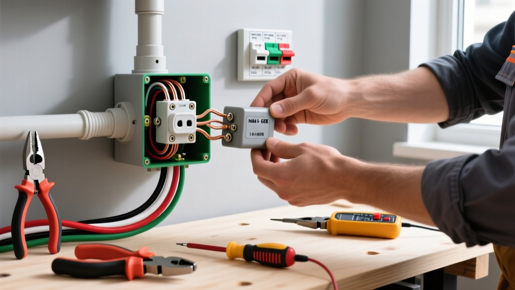
If you need to wire a single outlet, the direct answer depends on your circuit breaker size. For a standard 15-amp branch circuit, use 14/2 NM-B copper wire and a 15A tamper-resistant (TR) duplex receptacle. For a 20-amp circuit, use 12/2 NM-B copper wire and a 20A TR receptacle. The wire color mapping is universal across both: the black (hot) wire lands on the brass terminal, the white (neutral) wire lands on the silver terminal, and the bare or green (ground) wire lands on the green terminal.
The Default Setup: 15A vs 20A Single Outlet Decision
Before stripping any wire, you must match the receptacle rating and wire gauge to the overcurrent protective device (the breaker) feeding the circuit. The National Electrical Code (NEC) strictly prohibits placing a 20A receptacle on a 15A circuit, and while a 15A receptacle is technically allowed on a 20A circuit in multi-outlet branch circuits, a single-outlet dedicated circuit requires the receptacle rating to match the breaker rating exactly.
| Circuit Breaker Size | Wire Gauge (Copper) | Receptacle Rating | Best Application |
|---|---|---|---|
| 15 Amp | 14 AWG (14/2 NM-B) | 15A TR Duplex | Bedrooms, living rooms, hallways, general lighting |
| 20 Amp | 12 AWG (12/2 NM-B) | 20A TR Duplex | Kitchens, bathrooms, garages, dedicated appliance circuits |
Tools and Materials for a Code-Compliant Install
Professional results require professional tooling. Skip the cheap multi-tools and use dedicated wire strippers to avoid nicking the copper conductor, which creates a hot spot and a future failure point.
Required Tools
- Wire Strippers: Klein Tools 11055 (for 10-18 AWG solid wire) to cleanly strip insulation without scoring the copper.
- Non-Contact Voltage (NCV) Tester: Milwaukee or Fluke NCV pen to verify the presence of voltage before touching wires.
- Digital Multimeter: Fluke 117 or equivalent true-RMS meter with CAT III 600V rating for definitive dead-front verification and final testing.
- Torque Screwdriver: Klein 32500 series or similar, calibrated to the manufacturer's specified inch-pounds (typically 14 in-lbs for standard 15A/20A side-wire terminals). NEC 110.14(D) mandates that connections be torqued to manufacturer specifications.
- Lineman's Pliers: For twisting wire nuts and bending J-hooks.
Required Materials
- Receptacle: 15A or 20A Tamper-Resistant (TR) duplex receptacle (commercial grade preferred for back-wire clamps, but residential side-wire is standard).
- Wire Nuts: Ideal 341 (yellow) or 314 (tan) for joining 14 AWG or 12 AWG pigtails.
- Cable: 14/2 NM-B (for 15A) or 12/2 NM-B (for 20A) if running a new home run.
Mains Safety: De-Energize and Verify Dead
- Identify and Kill the Breaker: Turn off the specific branch circuit breaker in your main or subpanel. Place a piece of tape over the breaker with your name and the date to prevent someone from accidentally turning it back on while you are working.
- Initial NCV Sweep: Insert your Non-Contact Voltage tester into the top and bottom slots of the existing outlet. The tester should remain dark and silent. If it beeps or lights up, you have turned off the wrong breaker. Stop and re-evaluate.
- Multimeter Verification: Set your digital multimeter to AC Volts (V~). Insert the black probe into the COM jack and the red probe into the V/Ω jack. Test from the narrow slot (hot) to the wide slot (neutral), then from the narrow slot to the ground hole (the U-shaped slot). Both readings must be exactly 0.0V.
- Test Your Tester: To ensure your meter didn't blow an internal fuse and give you a false "dead" reading, test it on a known live circuit (like an extension cord plugged into a different, confirmed live room) immediately after verifying the target outlet is dead.
Step-by-Step: Wiring the Receptacle Terminals
With the box confirmed dead, remove the old receptacle. If you are wiring a new box, ensure the cable sheath enters the box by at least 1/4 inch and that you have at least 6 inches of conductor length extending past the front edge of the box.
- Strip the Conductors: Using your Klein 11055 strippers, remove exactly 3/4 inch of insulation from the black, white, and bare ground wires. Do not nick the copper. If you score the metal, cut it off and strip again.
- Form the J-Hooks: Grip the stripped end of the wire with your lineman's pliers and bend it into a tight, 180-degree J-hook. The hook should be uniform so it wraps cleanly around the terminal screw without overlapping the insulation or exposing bare copper past the washer.
- Terminate the Ground (Bare/Green): Loop the bare copper (or green insulated) wire J-hook clockwise around the green ground screw at the bottom or end of the receptacle yoke. Tighten with your torque screwdriver until the tool clicks (usually 14 in-lbs). The clockwise loop ensures the screw pulls the wire tighter as you drive it, rather than pushing it out.
- Terminate the Neutral (White): Loop the white wire J-hook clockwise around one of the silver terminal screws on the left side of the yoke. Torque to spec. Ensure no bare copper is visible outside the terminal plate, and that the wire insulation is not pinched under the screw head.
- Terminate the Hot (Black): Loop the black wire J-hook clockwise around one of the brass terminal screws on the right side of the yoke. Torque to spec.
Mnemonic: "Black to Brass gets you off your..." (you know the rest). Black is hot, brass is hot. White is neutral, silver is neutral.
- Fold and Secure: Gently fold the wires into the back of the electrical box. Push the ground wire in first, followed by the neutral whites, and finally the hot blacks. Mount the receptacle yoke to the box using the provided 6-32 machine screws, ensuring the device sits flush and level against the drywall or plaster ring.
The Most Common Botch: Push-In Backwiring and Broken Tabs
When learning how to wire a single outlet, most DIYers make one of two critical errors that lead to callbacks, thermal damage, or dead circuits.
Botch 1: Using Push-In Backwire Holes
Standard residential receptacles feature small holes on the back of the plastic body. These are "push-in" or "backstab" terminals that rely on a small internal spring-metal clip to grip the stripped wire. Symptom: The outlet works fine for a phone charger, but when you plug in a 12A vacuum cleaner, the voltage drops, the plug gets hot, or the power intermittently cuts out. The Fix: Never use push-in backstab holes. The spring metal has a different thermal expansion coefficient than the copper wire. Over months of heating and cooling under load, the spring loosens, creating a high-resistance connection that leads to arcing and melted plastic. Always use the side-wire screw terminals, or upgrade to a "commercial spec grade" receptacle (like the Leviton 5262-SW) that features true back-wire clamps operated by the side screws.
Botch 2: Breaking the Connecting Fins (Tabs)
Between the two brass screws (and the two silver screws) on a standard duplex receptacle, there is a small metal connecting fin called a "tab." Symptom: You wire the outlet, turn on the breaker, and only the top half of the outlet has power. The bottom half is dead. The Fix: A single outlet wired to a single cable does not require the tabs to be broken. Break the tab only when you are wiring a "split-wired" receptacle (where the top half is always hot, and the bottom half is controlled by a wall switch). If you are just replacing a standard outlet, leave both the brass and silver tabs completely intact.
Verify and Test: Expected Meter Readings
Before plugging in any appliances, you must verify the wiring is correct and the grounding path is solid. According to the U.S. Consumer Product Safety Commission (CPSC), improper grounding and reversed polarity are leading causes of residential electrical shocks.
Turn the breaker back on. Set your multimeter to AC Volts and take the following measurements directly at the receptacle slots:
| Probe Placement | Expected Reading | What It Means If It's Wrong |
|---|---|---|
| Hot (Narrow Slot) to Neutral (Wide Slot) | 114V - 126V AC | Reading 0V: Open hot or open neutral. Reading ~240V: Lost neutral on a multi-wire branch circuit. |
| Hot (Narrow Slot) to Ground (U-Slot) | 114V - 126V AC | Reading 0V: Open ground or ground not bonded to neutral at the main panel. |
| Neutral (Wide Slot) to Ground (U-Slot) | Less than 2.0V AC | Reading > 2V: High-resistance neutral connection, shared neutral overload, or a floating ground. |
For a final visual check, plug in a standard 3-light receptacle tester (like the Klein Tools RT210). For a correctly wired 15A or 20A single outlet, you should see two yellow lights illuminated (or the specific pattern indicated on the tester's legend for "Correct"). If you see a red light, you have reversed hot and neutral (the black and white wires are on the wrong screws). Turn the breaker back off and swap the wires on the brass and silver terminals.
By following this exact sequence—matching the breaker to the wire gauge, terminating to the correct colored screws, torquing to spec, and verifying with a multimeter—you ensure a safe, code-compliant installation that will not degrade under thermal cycling. For deeper guidance on receptacle placement and spacing, always consult the latest edition of NFPA 70 and manufacturer testing documentation.