
The Prototype-to-Production Compliance Gap
Connecting a 16x2 LCD to an Arduino Uno using a breadboard and loose Dupont jumper wires is a rite of passage for electronics hobbyists. However, when that same arduino lcd wiring topology is transitioned into a commercial, industrial, or medical product, the rules change dramatically. What works on a lab bench will almost certainly fail a formal compliance inspection. As of 2026, regulatory bodies and certification labs (NRTLs) scrutinize low-voltage DC wiring harnesses just as heavily as mains AC wiring when evaluating products for safety, electromagnetic compatibility (EMC), and long-term reliability.
Whether you are designing an IoT environmental monitor, a commercial point-of-sale display, or an industrial control panel interface, your LCD wiring must adhere to stringent standards. This guide breaks down the inspection criteria for Arduino-based LCD wiring harnesses, focusing on IPC cable assembly standards, FCC radiated emissions, and industrial safety codes.
IPC-A-620 Standards for LCD Wiring Harnesses
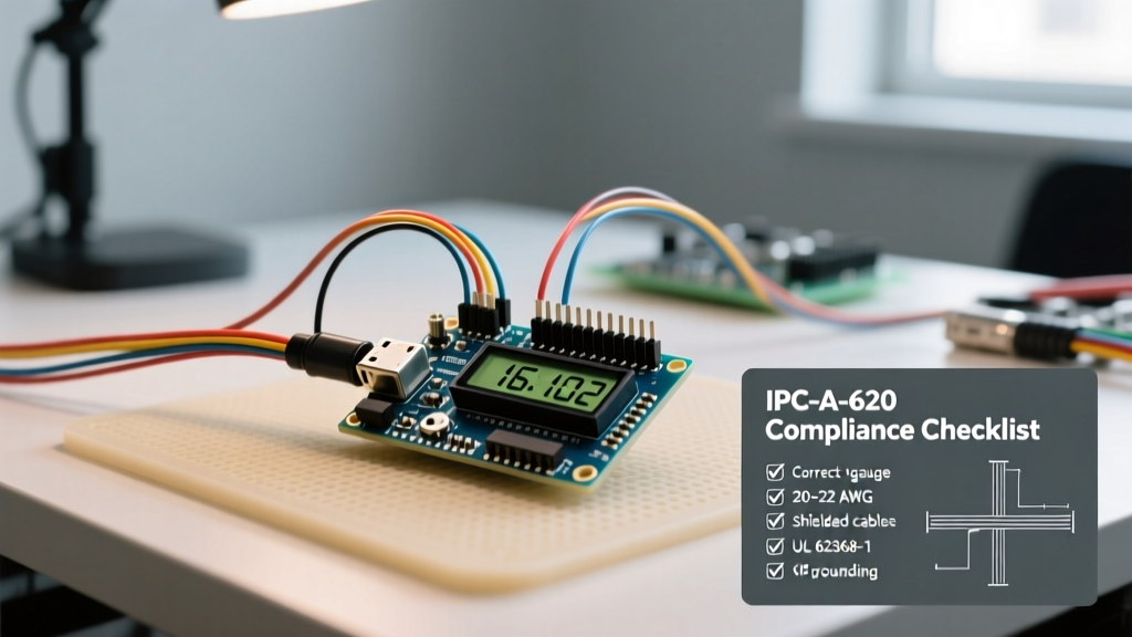
When an inspector evaluates the physical wiring harness connecting your microcontroller to the LCD module, they are typically referencing the IPC-A-620 standard for cable and wire harness assemblies. For commercial electronics, Class 2 (Dedicated Service) is usually required, while industrial or life-safety applications demand Class 3 (High Performance).
Wire Gauge and Insulation Ratings
Standard LCDs like the Hitachi HD44780 or I2C variants draw minimal current (typically 20mA to 80mA for the backlight). While AWG 28 or 30 might handle the current, compliance inspections require mechanical robustness. Inspectors look for AWG 24 to AWG 26 stranded wire. Furthermore, the insulation must carry a recognized safety mark, such as UL1007 (PVC, 300V, 80°C) or UL1571. Using unmarked, generic ribbon cable from overseas marketplaces is an immediate red flag during a UL 62368-1 audit, as the flammability rating (VW-1) cannot be verified.
Crimp Quality and Pull-Force Testing
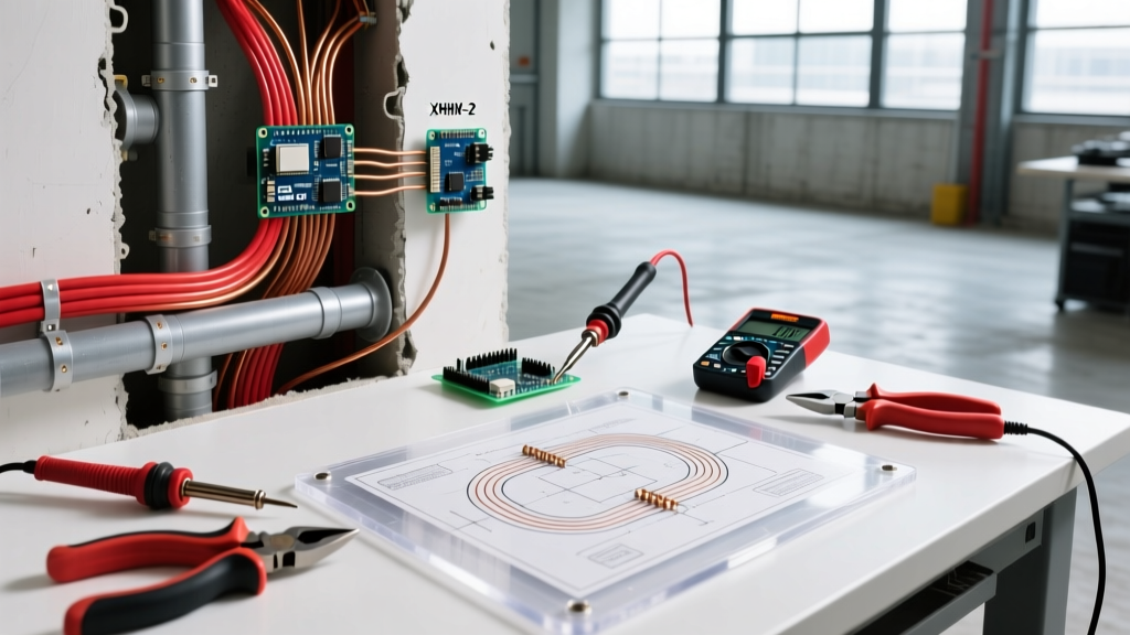
If your Arduino LCD wiring terminates in JST-XH, Molex PicoBlade, or standard 2.54mm headers, the crimp quality is a primary inspection point. Under IPC-A-620, a compliant crimp must exhibit no visible wire strand damage, proper insulation grip, and a specific pull-force resistance. For AWG 26 wire, a compliant crimp should withstand a minimum pull force of 3.5 lbs (15.5 N) without the wire slipping from the terminal. Hand-crimped Dupont connectors using cheap pliers routinely fail this test and are strictly prohibited in certified production runs. Expect to pay $1.50 to $3.50 per unit for custom-molded, IPC-compliant harnesses at volume, compared to $0.40 per pin for hand-crimped prototypes.
Signal Integrity: Parallel HD44780 vs. I2C PCF8574
The physical routing and topology of your Arduino LCD wiring heavily influence whether the device will pass functional inspections and EMC testing. Inspectors and compliance engineers evaluate the wiring diagram to identify potential signal integrity bottlenecks.
| Feature | Parallel (HD44780 Direct) | I2C (PCF8574 Backpack) |
|---|---|---|
| Wire Count | 6 to 11 wires (Data + Control + Power) | 4 wires (VCC, GND, SDA, SCL) |
| Max Unshielded Length | ~15 cm (6 inches) before signal degradation | ~30 cm (12 inches) limited by bus capacitance |
| EMI Susceptibility | High (Wide ribbon cables act as antennas) | Moderate (Requires proper pull-up routing) |
| Inspection Focus | Crosstalk, ground return paths, skew | Bus capacitance (400pF limit), pull-up resistor placement |
The I2C Capacitance Trap
When using an I2C LCD backpack (typically based on the Texas Instruments PCF8574 or NXP PCA9515), the wiring harness adds parasitic capacitance. The I2C specification strictly limits total bus capacitance to 400pF. A standard 26AWG ribbon cable adds roughly 15pF to 20pF per foot. If your inspection reveals a 3-foot cable run routed alongside a metal chassis, the capacitance will spike, causing the SDA/SCL edges to round off. The LCD will fail to initialize during functional testing. For longer runs in compliant designs, engineers must integrate bus extenders like the NXP P82B715 to buffer the signals.
EMC Compliance and FCC Part 15 Radiated Emissions
One of the most common reasons consumer electronics fail FCC Part 15 Class B radiated emissions testing is poor low-voltage wiring practices. The Arduino's digital clock signals and the PWM signals driving the LCD backlight can couple onto the LCD wiring harness.
Inspector's Note: A 16-pin flat ribbon cable connecting a microcontroller to a parallel LCD acts as a highly efficient dipole antenna. The harmonics of the Arduino's 16MHz crystal oscillator will radiate directly off these wires, frequently causing failures in the 30MHz to 100MHz range during pre-compliance sweeps.
To pass EMC inspections, the Arduino LCD wiring must be designed with EMI mitigation in mind:
- Twisted Pairs: For I2C wiring, twist the SDA wire with a ground wire, and the SCL wire with another ground wire. This minimizes the loop area and drastically reduces radiated emissions.
- Shielding: If the LCD must be mounted more than 10cm from the main PCB, use a shielded cable assembly with the shield tied to chassis ground at the microcontroller end only (to prevent ground loops).
- Ferrite Beads: Integrating a snap-on ferrite core (e.g., Wurth Elektronik 74271132) near the PCB header can suppress high-frequency common-mode noise traveling down the LCD harness.
Industrial Control Panels and NFPA 79
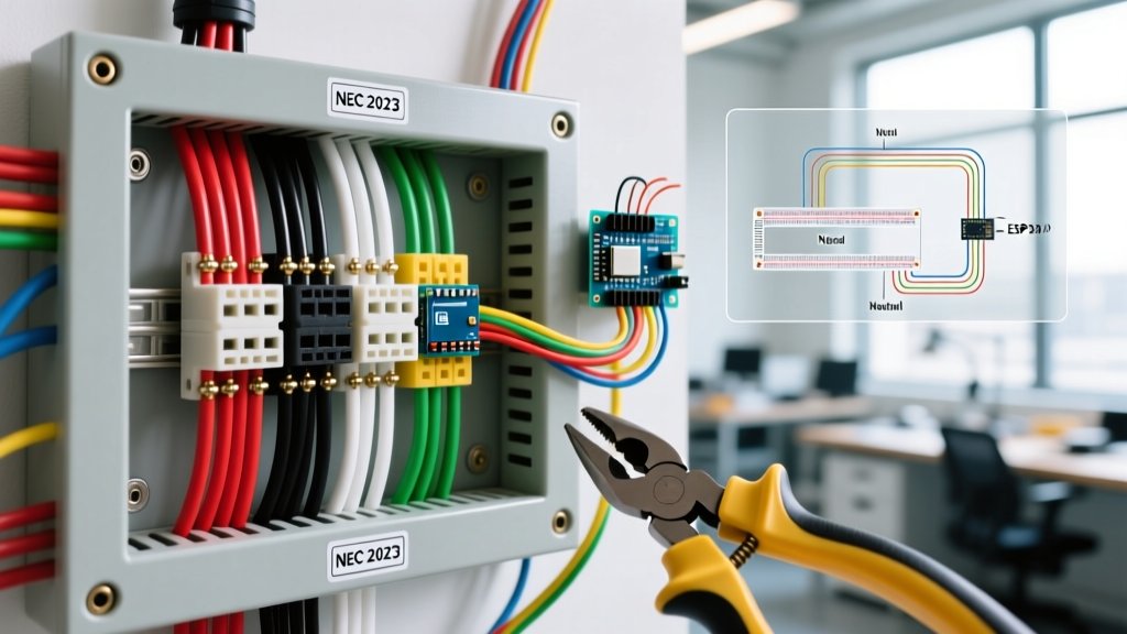
If your Arduino-based LCD is being deployed as an HMI (Human-Machine Interface) inside an industrial control cabinet, the wiring must comply with NFPA 79 (Electrical Standard for Industrial Machinery). Inspectors enforcing NFPA 79 and UL 508A are primarily concerned with the physical separation of voltage classes.
The 5V DC wiring for the Arduino and LCD is classified as a Class 2 circuit, while the motor contactors and PLC I/O operating at 120VAC or 240VAC are Class 1. NFPA 79 strictly mandates that Class 2 wiring must be routed in separate wire ducts or separated by a physical grounded metal barrier from Class 1 wiring. If an inspector opens a control panel and finds the Arduino LCD ribbon cable zip-tied to a 120VAC VFD power cable, the panel will fail inspection immediately due to the risk of inductive coupling and catastrophic fault hazards.
Common Inspection Failure Modes & Troubleshooting
Based on recent compliance audits, here are the most frequent edge cases and failure modes encountered during Arduino LCD wiring inspections:
- Ground Bounce via Shared Returns: Routing the LCD backlight ground through the same thin wire as the logic ground causes voltage drops when the backlight PWM cycles. This results in 'ground bounce,' resetting the Arduino. Fix: Use a dedicated AWG 22 ground wire for the backlight LED array.
- Missing Strain Relief: The connector at the LCD PCB lacks a mechanical locking mechanism. Vibration testing (ISTA 3A) causes the header to back out, leading to intermittent display failures. Fix: Specify JST-XH connectors with positive locking tabs or apply RTV silicone for mechanical strain relief.
- Improper Pull-Up Routing: I2C pull-up resistors (typically 4.7kΩ) are placed on the LCD backpack rather than the Arduino master PCB. Long harnesses cause the pull-up voltage to sag at the master end. Fix: Always place pull-up resistors within 2cm of the microcontroller's SDA/SCL pins.
Final Thoughts on Production Readiness
Mastering arduino lcd wiring for compliance means looking beyond basic connectivity. It requires an understanding of parasitic capacitance, radiated emissions, and mechanical reliability standards. By upgrading from hobbyist jumper wires to UL-rated, IPC-crimped harnesses, and respecting EMC routing rules, you ensure your device will not only function flawlessly but will also sail through rigorous third-party inspections and achieve market certification without costly redesigns.