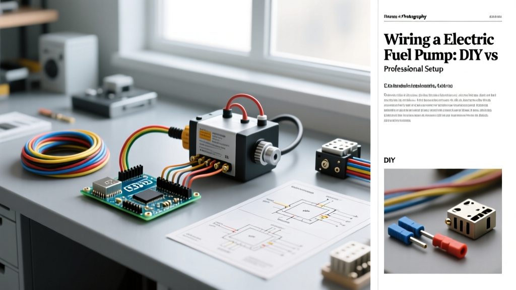

The Stakes: Why Fuel Pump Wiring Demands Precision
When enthusiasts tackle an engine swap, an EFI conversion, or a high-performance restomod, the fuel delivery system is often the final hurdle. While mechanical pumps are largely relegated to history, modern electronic fuel injection (EFI) and direct injection (GDI) systems rely entirely on high-pressure electric pumps. However, many builders treat wiring a electric fuel pump as an afterthought, simply splicing into an existing 12V source or relying on a generic universal harness. This is a critical error.
The stakes of improper fuel pump wiring extend far beyond a tripped breaker or a dead pump. A poorly wired circuit suffers from voltage drop, which directly reduces the pump's rotational speed. In a high-load scenario—such as wide-open throttle (WOT) on a supercharged application—a 1.5-volt drop can reduce fuel flow by up to 20%. The engine runs lean, cylinder temperatures spike, and catastrophic detonation follows. In 2026, with ECU tuning pushing the absolute limits of air-fuel ratios, delivering consistent, unimpeded voltage to your fuel pump is non-negotiable.
Core Electrical Requirements for Modern EFI Pumps
Current Draw and Voltage Drop Realities
To understand the divide between amateur and professional installations, you must first understand the electrical demands of modern pumps. A standard in-tank Walbro GSS342 (255 LPH) draws approximately 13 to 15 amps continuously at 14 volts, but its inrush current upon startup can spike past 25 amps. Higher-flowing units, like the Aeromotive 340 Stealth (Part #11540), can pull 18 amps continuously under high pressure.
According to wiring standards outlined by SAE International, automotive circuits must be designed to minimize voltage drop. If a DIYer uses 14 AWG wire for a 12-foot run from the front-mounted battery to the rear fuel tank, the resistance will cause a voltage drop of roughly 0.8 volts under a 15A load. The pump receives 12.2V instead of the alternator's 13.8V. Professionals calculate wire gauge based on the total circuit length (positive and ground) and the specific amperage, typically mandating 10 AWG or even 8 AWG cross-linked polyethylene (TXL) wire for high-amperage runs.
The DIY Route: Cost, Execution, and Hidden Pitfalls
The DIY approach to wiring a electric fuel pump is heavily favored by budget-conscious builders and weekend warriors. The fundamental logic is sound: use a relay to isolate the high-current pump circuit from the low-current ECU trigger signal. However, the execution is where amateur builds frequently fail.
Typical DIY Bill of Materials (2026 Pricing)
- Standard Bosch-style 30A Mini Relay: $8 - $12
- 10 AWG PVC THHN Wire (15 ft): $12 - $18
- Basic Inline Fuse Holder & 25A ATC Fuse: $8 - $12
- Non-Weatherpack Ring/Spade Terminals: $10
- Total Estimated Cost: $38 - $52
Critical DIY Failure Modes
- The Grounding Fallacy: The most common DIY mistake is grounding the pump or relay to a painted chassis surface or a rusty bolt. Paint and rust act as resistors. A professional will grind the chassis down to bare metal, apply a conductive anti-oxidant paste, and use a star washer to bite into the steel.
- Under-Hood PVC Meltdown: Standard PVC-insulated wire (like THHN) becomes brittle and melts when exposed to modern under-hood temperatures, which frequently exceed 120°F (49°C) near exhaust headers. This leads to dead shorts against the chassis.
- Skipping the Inertia Switch: In the event of a collision, a damaged fuel line combined with a pump that continues to run will rapidly spray atomized fuel onto hot exhaust components. Bypassing the factory inertia (rollover) switch to "simplify" the wiring is a severe fire hazard.
Expert Warning: Never route high-current fuel pump wiring through the same firewall grommet as your ECU sensor harnesses. The electromagnetic interference (EMI) generated by the pump's commutator can induce noise in low-voltage O2 sensor and MAP signal wires, causing erratic fuel trims.
The Professional Standard: What You Pay For
When you hand your vehicle over to a specialized EFI wiring shop, you are not just paying for labor; you are paying for risk mitigation, advanced materials, and system integration. As of 2026, specialized automotive electrical shops charge between $135 and $185 per hour. A comprehensive fuel system wiring overhaul typically takes 5 to 7 hours, bringing the labor cost to $675–$1,295, plus premium materials.
Pro-Level Materials and Techniques
Professionals abandon hardware-store wire in favor of TXL (Thin-wall Cross-linked) or PTFE (Teflon) wire, which withstands temperatures up to 250°C and resists fuel and oil degradation. Connections are never crimped with generic pliers; pros use ratcheting crimpers calibrated for specific terminals, such as Delphi Weather-Pack or Deutsch DT series connectors, ensuring a gas-tight seal that prevents corrosion.
Furthermore, modern returnless fuel systems require Pulse Width Modulation (PWM). Running a high-pressure pump at 100% duty cycle in a returnless setup causes the fuel to heat up in the rails, leading to vapor lock. Professionals integrate PWM controllers (like the Aeromotive 13301 or Holley VR2) that use a solid-state relay (SSR) to pulse the pump at 40% duty cycle at idle, ramping to 100% only under heavy load. This extends pump life by up to 300% and stabilizes fuel temperatures.
Head-to-Head Comparison Matrix
| Feature | Typical DIY Installation | Professional EFI Installation |
|---|---|---|
| Total Cost (Parts + Labor) | $40 - $60 (Owner Labor) | $850 - $1,500+ |
| Wire Insulation | PVC / THHN (Low heat resistance) | TXL / PTFE (High heat/chemical resistance) |
| Connectors | Open-barrel crimps, electrical tape | Sealed Deutsch / Weather-Pack, heat-shrink |
| Relay Type | Mechanical Bosch-style (Arcing over time) | Solid-State (SSR) or Heavy-Duty Contactor |
| Voltage Control | Static 12V (100% Duty Cycle) | PWM Controller (Variable Duty Cycle) |
| Firewall Pass-through | Drilled hole with RTV silicone | Sealed CNC bulkhead connectors |
The Ultimate Wiring Topology (Step-by-Step)
Whether you are executing a high-end DIY build or verifying a shop's work, the correct topology for a standard return-style EFI pump must follow this exact path to ensure safety and performance. Technical guidelines from Painless Performance and other harness manufacturers emphasize the following sequence:
- Power Source: Connect 10 AWG TXL wire directly to the battery positive terminal or main distribution stud.
- Primary Fusing: Install a 25A or 30A ANL/ATC fuse within 12 inches of the power source. This protects the entire length of the wire run in case of a dead short.
- Relay Feed (Pin 30): Route the fused 10 AWG wire to Pin 30 of a heavy-duty 40A relay.
- Pump Feed (Pin 87): Run 10 AWG wire from Pin 87, through a sealed firewall bulkhead, through the factory inertia switch, and to the fuel pump positive terminal.
- ECU Trigger (Pin 86): Connect Pin 86 to the ECU's dedicated fuel pump prime output (usually a low-current ground or 12V signal, depending on the ECU brand).
- Ground & Flyback Protection (Pin 85): Ground Pin 85 to the chassis. Critical: Solder a 1N4007 flyback diode across Pins 85 and 86 (stripe facing Pin 86). This absorbs the inductive voltage spike when the relay coil de-energizes, protecting sensitive ECU driver transistors from frying.
- Pump Ground: Use 10 AWG wire to ground the pump directly to the chassis near the tank, ensuring bare metal contact.
Verdict: When to Wrench and When to Outsource
So, who should tackle wiring a electric fuel pump? If you are building a traditional carbureted restomod with a low-pressure, low-amperage pump (like a Holley Red or Carter P4070 drawing under 5 amps), a well-executed DIY harness using proper relays and fuses is perfectly adequate and cost-effective.
However, if your 2026 build involves a high-pressure GDI system, a flex-fuel setup requiring variable pressure mapping, or a returnless EFI system prone to vapor lock, the complexity demands professional intervention. The cost of a PWM controller, specialized bulkhead connectors, and oscilloscope-tested wiring is a fraction of the cost of replacing a melted harness, a fried ECU, or worse, a burned-down garage. Assess your system's amperage demands, respect the physics of voltage drop, and choose your wiring strategy accordingly. For further reading on high-flow fuel system dynamics, consult the engineering tech articles provided by Aeromotive before cutting your first wire.