
Bridging Material Science and Field Diagnostics
When electricians and engineers ask, why is copper used for electrical wiring, the standard answer usually revolves around its superior conductivity and ductility. However, understanding the exact metallurgical properties of copper is not just an academic exercise; it is the foundational knowledge required to troubleshoot complex electrical failures. In 2026, with copper commodity prices hovering around $4.20 to $4.50 per pound and the cost of a standard 250-foot spool of 12/2 NM-B Romex averaging $125, replacing damaged wiring is a significant expense. Therefore, accurately diagnosing copper-specific failure modes is critical for residential and commercial electricians.
This troubleshooting guide explores the physical properties that make copper the industry standard and translates those properties into actionable diagnostic frameworks for field technicians. According to the Copper Development Association (CDA), copper's unique atomic structure allows for high electron mobility, but this same structure introduces specific vulnerabilities—such as cold flow and thermal annealing—when subjected to improper installation or environmental stress.
Diagnostic Premise: Every copper wiring failure is a direct result of its material properties reacting to mechanical, thermal, or chemical stress. By understanding why copper behaves the way it does, you can isolate where and how it is failing in a circuit.
The Physics of Copper: Why It Dominates the Market
Before troubleshooting, we must establish the baseline metrics of copper. Copper is the universal standard for electrical conductivity, measured against the International Annealed Copper Standard (IACS), where pure copper is assigned a 100% conductivity rating. Aluminum, its primary competitor, sits at roughly 61%. This means a copper wire can carry significantly more current at a smaller gauge than aluminum, reducing voltage drop and allowing for tighter bending radii in conduit.
Key Material Properties and Their Troubleshooting Implications
- High Ductility & Tensile Strength: Copper can be drawn into thin wires and bent repeatedly without snapping. Troubleshooting Implication: If a copper wire is snapping or fracturing at the termination point, it has likely been over-stripped, nicked by wire strippers, or subjected to severe harmonic vibration.
- Thermal Expansion Coefficient: Copper expands and contracts with heat. Troubleshooting Implication: Repeated thermal cycling under heavy loads can cause 'creep' (cold flow), leading to loose terminal connections and subsequent arcing.
- Oxidation Profile: Unlike aluminum oxide, which is highly resistive and insulative, copper oxide remains somewhat conductive. Troubleshooting Implication: While copper connections are less prone to catastrophic thermal runaway from oxidation than aluminum, severe galvanic corrosion will still increase resistance and trigger voltage drops.
Troubleshooting Failure Mode 1: Copper Creep and Terminal Loosening
One of the most insidious issues in electrical panels and receptacles is 'creep' or cold flow. Even at room temperature, copper under constant mechanical pressure (like a tightened terminal screw) will slowly deform and flatten over time. When combined with thermal cycling—heating up under load and cooling down when the circuit is idle—the wire shrinks and expands, eventually creating a microscopic gap between the wire and the terminal.
Diagnostic Steps for Creep-Induced Failures
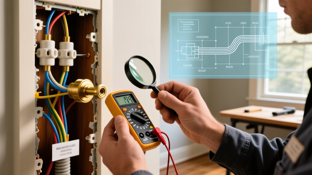
- Thermal Imaging Scan: Use a high-resolution thermal imager, such as the Fluke Ti480 PRO, to scan the panel under a sustained load (at least 70% of the breaker's rated capacity). A temperature delta (ΔT) of more than 15°C (27°F) between the breaker terminal and the bus bar indicates a high-resistance connection caused by creep.
- Torque Verification: The National Fire Protection Association (NFPA) strictly mandates the use of calibrated torque tools in NEC Article 110.14(D). Do not rely on the 'quarter-turn past snug' method. For a standard 12 AWG solid copper wire on a 20-ampere receptacle, the manufacturer's specified torque is typically 25 in-lbs. Use a Wiha insulated torque screwdriver to verify the connection.
- Visual Inspection for Arcing: If creep has progressed to arcing, you will find black soot or pitting on the terminal screw. The copper wire itself may show signs of localized annealing (discoloration to a dark, dull brown or black) near the termination point.
Troubleshooting Failure Mode 2: Galvanic Corrosion and Oxidation
While copper oxide is less resistive than aluminum oxide, copper is highly susceptible to galvanic corrosion when it comes into direct contact with dissimilar metals in the presence of an electrolyte (like ambient humidity). This is frequently seen in outdoor disconnects, HVAC condenser whips, or when copper wires are improperly terminated on aluminum-rated lugs without proper preparation.
Identifying and Remediating Corrosion
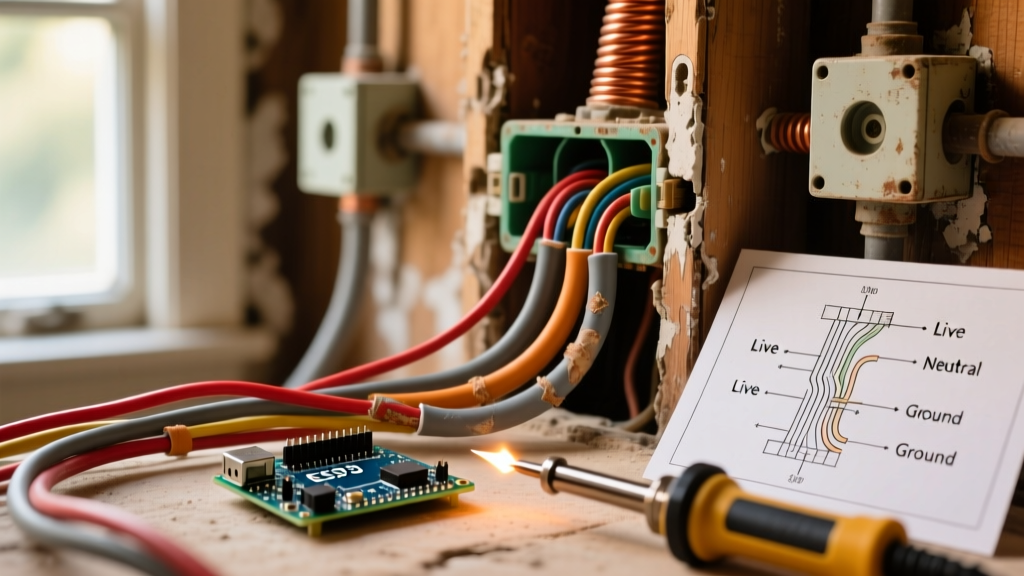
Corrosion manifests as a green or blue-green patina (copper carbonate/copper chloride) creeping up the strands of the wire. This crystalline structure acts as a semiconductor, creating a non-linear resistance that can cause erratic voltage drops and interfere with sensitive digital electronics and smart home modules.
- The Fix: Cut back the wire past the visible green oxidation. Strip the fresh copper and apply an antioxidant joint compound (such as Noalox or Penetrox). Note: Antioxidant pastes are not just for aluminum; they are highly recommended for copper-to-aluminum transitions and outdoor copper terminations to seal out moisture and prevent galvanic action.
- Pigtail Verification: If you are troubleshooting an older home where copper was spliced to legacy aluminum branch wiring, ensure the pigtails were done using COPALUM connectors or AlumiConn lugs, and that the copper side was not crushed or over-torqued during the retrofit.
Troubleshooting Failure Mode 3: Thermal Annealing from Overcurrent
Copper is a relatively soft metal. When subjected to temperatures exceeding 392°F (200°C), copper undergoes a process called annealing, where its crystalline structure realigns, causing the metal to lose its tensile strength and become overly soft and brittle upon cooling. This frequently occurs when a circuit is chronically overloaded, or when a loose neutral on a multi-wire branch circuit (MWBC) causes severe overvoltage and subsequent overheating.
Testing for Annealed Copper
Annealed copper is a severe fire hazard because it loses its mechanical integrity. If a short circuit occurs, the electromagnetic forces can physically rip annealed copper wires apart from their terminals.
- The Bend Test: During a panel inspection, gently bend the 12 AWG or 10 AWG copper conductors near the breaker. Healthy copper has a distinct, springy resistance. Annealed copper will feel mushy, bend with zero resistance, and may snap if bent back and forth more than twice.
- Insulation Check: Annealing is almost always accompanied by insulation degradation. If the THHN or XHHW-2 insulation feels sticky, cracked, or easily flakes off when you scrape it with a fingernail, the wire has been subjected to extreme heat. The entire run must be replaced.
Material Comparison Matrix: Copper vs. Alternatives
When troubleshooting, you must know what material you are working with. The rise of Copper Clad Aluminum (CCA) in counterfeit or substandard extension cords and cheap ethernet cables has introduced new failure points in 2026. Here is how copper compares to common alternatives in the field.
| Property | Pure Copper (THHN/NM-B) | Aluminum (XHHW-2) | Copper Clad Aluminum (CCA) |
|---|---|---|---|
| Conductivity (IACS) | 100% | 61% | ~65-70% |
| Thermal Expansion | Low (Requires standard torque) | High (Prone to creep) | High (Mismatched core/clad) |
| Oxide Conductivity | Semi-Conductive | Highly Insulative | Insulative (if clad is breached) |
| Primary Failure Mode | Terminal loosening, Annealing | Cold flow, Oxidation fires | Galvanic rot, Core snapping |
| NEC Acceptance (Branch) | Fully Approved | Approved (AA-8000 series) | Banned for NEC branch wiring |
Essential Diagnostic Toolkit for Copper Troubleshooting
To properly diagnose copper wiring issues in modern electrical systems, rely on data rather than guesswork. The Electrical Safety Foundation International (ESFI) emphasizes that modern electrical loads require precise verification. Equip your troubleshooting kit with the following:
- True-RMS Clamp Meter with Inrush: Essential for measuring the actual current draw and identifying if a circuit is operating near its continuous load limit (80% of breaker rating), which accelerates thermal cycling and copper creep.
- Milliohm Meter: A standard multimeter cannot detect the micro-ohm resistance changes caused by early-stage copper oxidation or loose terminations. A dedicated milliohm meter (like the Fluke 8845A or a specialized low-resistance ohmmeter) will reveal hidden voltage drop issues before they manifest as heat.
- Calibrated Torque Screwdriver: Mandatory for NEC compliance. Ensure it is calibrated annually to guarantee your terminations are applying the exact pressure required to counteract copper's natural tendency to cold-flow.
Summary: Leveraging Material Knowledge for Better Repairs
Understanding why is copper used for electrical wiring goes far beyond its high conductivity rating. Copper is chosen for its tensile strength, predictable thermal profile, and ductility. However, these exact traits dictate how it fails in the real world. By recognizing the signs of cold flow, galvanic corrosion, and thermal annealing, electricians can move past simple 'trial and error' repairs and implement permanent, code-compliant solutions. Whether you are tightening a loose neutral in a 200-amp residential panel or diagnosing a voltage drop in a commercial lighting circuit, respecting the metallurgy of copper is the key to long-term electrical safety and reliability.