
Decoding Tube Electrical Wiring in Modern Inspections
When electrical inspectors and the Authority Having Jurisdiction (AHJ) refer to tube electrical wiring, they are primarily addressing conduit-based raceway systems. In modern commercial and high-end residential construction, this encompasses Electrical Metallic Tubing (EMT), Flexible Metal Conduit (FMC), and Rigid Nonmetallic Conduit (PVC tubing). As we navigate the 2026 National Electrical Code (NEC) cycle, AHJs are applying unprecedented scrutiny to thermal management, fill capacities, and grounding continuity in these systems due to the increased amperage demands of smart building infrastructure and EV charging networks.
Passing a rough-in and final inspection for tube wiring requires more than just pulling wire through a pipe. It demands strict adherence to geometric limits, support spacing, and bonding protocols. This guide breaks down the exact metrics, failure modes, and compliance checkpoints that inspectors use to evaluate tube electrical wiring systems.
The Inspector's Matrix: Critical Compliance Metrics
Inspectors do not guess; they measure. Below is the quick-reference compliance matrix for the three most common tube wiring systems evaluated during commercial and residential rough-ins. Data aligns with the 2026 NEC updates.
| Tube Type | NEC Article | Max Fill (3+ Wires) | Max Support Spacing | Min Bending Radius (1/2 in.) | 2026 Avg. Material Cost |
|---|---|---|---|---|---|
| EMT (Steel) | Article 358 | 40% | 10 ft | 4 inches | $1.15 - $1.45 / ft |
| FMC (Flex) | Article 348 | 40% | 4.5 ft | 4 inches | $0.90 - $1.20 / ft |
| PVC (Sch 80) | Article 352 | 40% | 3 ft | 6 inches | $2.30 - $2.80 / ft |
Conduit Fill and the Physics of Jam Ratios
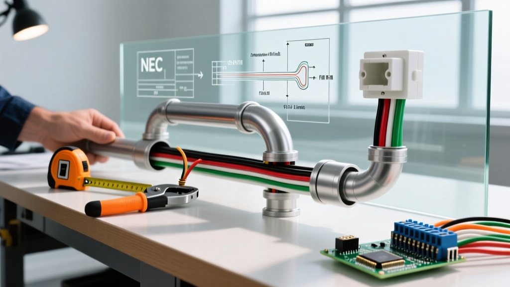
The most frequent point of failure during a tube electrical wiring inspection is improper conduit fill. According to Chapter 9, Table 1 of the NEC, the cross-sectional area fill limits are strictly enforced:
- 1 Conductor: 53% fill
- 2 Conductors: 31% fill
- 3 or more Conductors: 40% fill
However, inspectors in 2026 are increasingly calculating the Jam Ratio, a mathematical edge case that standard fill tables miss. The Jam Ratio dictates whether conductors will wedge against each other and the tube wall at a bend, causing catastrophic insulation damage during the pull.
Calculating the Jam Ratio
The formula for the Jam Ratio is the internal diameter (ID) of the tube divided by the outer diameter (OD) of a single conductor. If the result is between 2.8 and 3.2, a jam is highly likely at any bend.
Inspector's Insight: If you are pulling three 1/0 AWG THHN wires (OD = 0.454") into a 1-inch EMT (ID = 1.049"), your Jam Ratio is 1.049 / 0.454 = 2.31. Because this is below 2.8, the wires will lay flat and pull cleanly. However, if you attempt to pull three 2 AWG wires (OD = 0.414") into a 3/4-inch EMT (ID = 0.824"), the ratio is 1.99. While technically under the 40% fill rule, the physics of the bend will cause a jam, tearing the THHN insulation. Inspectors will flag this and mandate a larger tube size.
Bending, Securing, and Support Rules
Tube wiring must be installed without damaging the raceway or altering its internal geometry. Inspectors carry calipers and tape measures to verify these specific NEC mandates.
Flattening and Kinking Limits
Under NEC 358.22, the bending of EMT must not result in a reduction of the internal diameter that would damage the conductors or restrict the pull. Practically, AHJs measure the bend; if the tube is flattened by more than 10% of its original circular diameter, it is an automatic fail. Kinked tubing must be cut out and replaced. Using improper bending tools (like plumbing pipe benders) instead of calibrated EMT conduit benders is a primary cause of this violation.
Support and Securing Spacing
Tubing must be securely fastened to prevent sagging, which alters the gravitational pull on heavy copper conductors and stresses junction box knockouts.
- EMT (Steel): Must be secured within 3 feet of every outlet box, junction box, or fitting, and at intervals not exceeding 10 feet. (NEC 358.30)
- FMC (Flex): Must be secured within 12 inches of boxes and at intervals not exceeding 4.5 feet. (NEC 348.30)
- PVC Tubing: Requires support within 3 feet of boxes and every 3 feet for 1/2-inch through 1-inch diameters. (NEC 352.30)
Pro-Tip for 2026 Remodels: When retrofitting tube wiring in drop ceilings, inspectors will check that EMT is not simply resting on the ceiling grid. It must be independently supported by threaded rods or approved metal hangers attached to the building structure.
Grounding and Bonding in Metallic Tube Systems
One of the most heavily scrutinized aspects of metallic tube electrical wiring is its role as an Equipment Grounding Conductor (EGC). Under NEC 250.118, EMT and its associated fittings can serve as the EGC, provided the connections are tight and secure. However, there are critical exceptions where inspectors will demand a separate bare or green insulated copper grounding wire pulled inside the tube:
- FMC Length Limits: Flexible Metal Conduit can only be used as an EGC if the total length in any ground return path does not exceed 6 feet, and the circuit conductors are protected by an overcurrent device rated at 20 amps or less. If your FMC run is 8 feet, you must pull a separate ground wire.
- Vibration Environments: If the tube is connected to vibrating equipment (e.g., HVAC compressors, industrial motors), a separate EGC and a flexible bonding jumper are mandatory, as vibration will eventually loosen the tube fittings, breaking the ground path.
- Grounding Bushings: For FMC or IMC (Intermediate Metal Conduit) sized 1-1/4 inch or larger, inspectors will look for grounding bushings at the termination points to bond the tube to the box, especially if concentric or eccentric knockouts have been punched out.
For a deeper dive into bonding requirements and grounding electrode systems, refer to the technical bulletins published by Electrical Contractor Magazine (ECMag), which frequently breaks down complex NEC Article 250 applications for field electricians.
Common Failure Modes Flagged During Final Walkthroughs
Based on recent AHJ inspection data, the following edge cases frequently result in failed final inspections for tube wiring systems:
1. Using Plumbing Fittings for Electrical Runs
Using water pipe elbows or plumbing PVC cement on electrical PVC tubing is an immediate code violation. Electrical PVC (Schedule 40 and 80) requires specific solvent cements that do not degrade the dielectric properties of the tube, and fittings must be UL-listed for electrical use. Furthermore, plumbing sweeps have a much tighter radius than NEC-mandated electrical sweeps, which will cause wire insulation damage during pulling.
2. Missing Pulling Compound on Long Runs
While not always explicitly measured by an inspector, the result of skipping wire pulling lubricant is highly visible. If an inspector sees scraped, dull, or stretched THHN/XHHW insulation at the ends of a long tube run, they will reject the pull. The maximum pulling tension for copper conductors is calculated at 0.008 multiplied by the circular mil area of the conductor. Exceeding this stretches the copper, altering its resistance and creating a thermal hazard.
3. Unsealed Conduit Ends
During the rough-in phase, if tube ends are left open before the wires are pulled, moisture, concrete slurry, and debris can enter the raceway. Inspectors will reject any tube system that shows signs of internal debris or moisture ingress. All open tube ends must be capped with plastic bushings or electrical tape until the wire pull begins.
Step-by-Step Pre-Inspection Checklist
Before calling the AHJ for a tube electrical wiring inspection, site supervisors should run through this mandatory checklist to ensure compliance and avoid costly re-inspection fees:
- Verify Fill Capacity: Cross-reference the wire count and AWG against NEC Chapter 9, Table 4. Ensure no run exceeds 40% fill for 3+ wires.
- Check Support Spacing: Measure the distance between straps. Ensure EMT is strapped every 10 feet and within 3 feet of every box.
- Inspect Bends: Visually and physically check all bends for flattening. Ensure no bend exceeds 360 degrees total between pull points.
- Tighten Compression Fittings: Use a calibrated torque screwdriver on EMT set-screw and compression couplings to ensure the grounding path is continuous.
- Confirm Bushings: Verify that plastic or metal bushings are installed on all cut tube ends to protect wire insulation from sharp metal edges.
Mastering the nuances of tube electrical wiring inspections requires a blend of code knowledge and practical field geometry. By respecting the physical limits of the raceway and the strict bonding requirements of the NEC, contractors can ensure their installations are safe, efficient, and fully compliant on the first inspection attempt. For ongoing updates on OSHA workplace safety standards regarding temporary and permanent wiring methods, consult the OSHA Wiring Methods Standards portal.