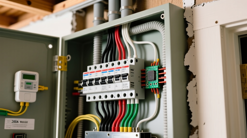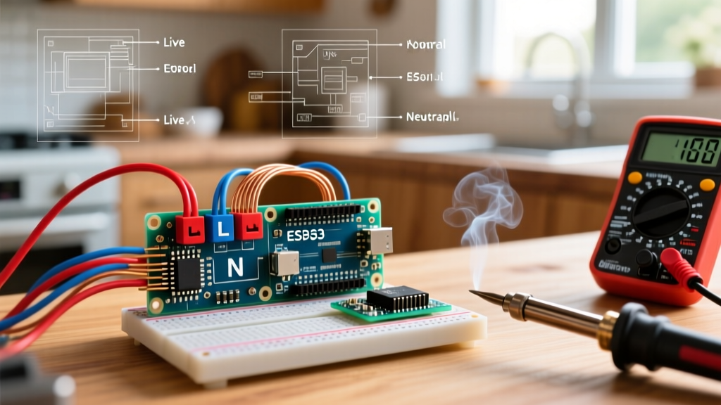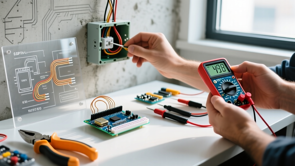

Smart home electrical wiring has evolved significantly by 2026, with the Matter protocol unifying ecosystems and Wi-Fi 6E reducing latency in high-density device environments. However, the physical infrastructure—specifically the copper in your walls—remains bound by the laws of physics. Troubleshooting smart home electrical wiring requires a hybrid mindset: you must think like a master electrician and a network engineer simultaneously. When a Lutron Caseta dimmer drops offline or a Shelly relay fails to actuate, the root cause is rarely the software; it is almost always a wiring topology mismatch, a missing neutral, or capacitive coupling.
⚠️ CRITICAL SAFETY WARNING: Always de-energize the circuit at the main breaker panel before opening any junction box. Verify zero voltage using a CAT III-rated multimeter (e.g., Fluke 117) or a non-contact voltage tester (e.g., Klein NCVT-3) on both line and load conductors. Never assume a switch is off just because the light is out.The 'No Neutral Wire' Dilemma: Symptoms and Fixes
The most common hurdle in retrofitting older homes with smart switches is the absence of a neutral wire. According to the National Fire Protection Association (NFPA), NEC Article 404.2(C) now mandates a neutral conductor at most switch locations, but homes built before 2011 frequently feature 'switch loops' containing only a Line (hot), Load (switched hot), and Ground wire.
Smart switches require continuous 120V power to operate their internal Wi-Fi, Zigbee, or Thread radios. If you wire a neutral-dependent switch (like the popular Shelly Plus 1PM, typically priced around $15) into a no-neutral box, the device simply will not boot. Conversely, if you install a no-neutral switch (like the Lutron Caseta PD-5S-DV, ~$60), it completes its internal circuit by leaking a tiny amount of current through the connected LED bulb.
Fixing the No-Neutral Bypass Issue
When using no-neutral switches with low-wattage LED bulbs (under 15W), the bulbs may flicker or glow faintly when turned off. This occurs because the smart switch's standby current is enough to partially charge the LED driver's capacitor.
- The Fix: Install a bypass resistor (such as the Lutron LUT-MLC, ~$10) directly at the light fixture, wiring it in parallel across the Load and Neutral wires at the ceiling canopy. This provides a path for the standby current, bypassing the LED driver entirely.
- Alternative: Upgrade to a smart switch that utilizes a MOSFET-based zero-crossing circuit, which minimizes leakage current, or pull a new 14/2 NM-B cable from the nearest junction box to provide a dedicated neutral.
Ghost Switching, LED Flickering, and Minimum Load
'Ghost switching'—where a smart relay clicks on and off randomly, or a smart bulb flashes without a command—is frequently blamed on network interference. In reality, it is often a physical wiring fault caused by capacitive coupling on long parallel wire runs.
| Symptom | Probable Wiring Fault | Diagnostic Tool | Exact Fix |
|---|---|---|---|
| Bulb glows when switch is OFF | Standby current leaking through LED driver | Clamp meter (mA setting) | Install LUT-MLC bypass at fixture |
| Random relay clicking (Ghosting) | Capacitive coupling / induced voltage | Fluke 117 (LoZ mode) | Add snubber capacitor or re-route cables |
| Dimmer buzzing loudly | Incompatible ELV/MLV transformer or loose neutral | Oscilloscope or visual inspection | Switch to ELV-rated dimmer (e.g., Lutron PD-10NXD) |
| Smart switch constantly rebooting | Voltage drop on long 14 AWG runs | Multimeter (AC Voltage) | Upgrade to 12 AWG wire or move transformer |
When long lengths of Line and Load wires run parallel inside the same conduit or Romex sheath, the alternating current in the Line wire induces a phantom voltage in the Load wire. A standard high-impedance digital multimeter might read 30V to 50V on the switched leg even when the smart switch is off. This induced voltage can trick sensitive smart relays into triggering. Using the 'LoZ' (Low Impedance) setting on a Fluke 117 multimeter will bleed off this ghost voltage, revealing the true 0V state and confirming capacitive coupling as the culprit.
Voltage Drop and Smart Relay Starvation
As highlighted by the U.S. Department of Energy, smart home devices draw continuous parasitic power. While a standard mechanical switch doesn't care about minor voltage drops, smart switches with ESP32 or Wi-Fi 6 chips require stable voltage to maintain network handshakes.
If you are wiring a smart switch at the end of a 75-foot run using 14 AWG wire on a 15-amp circuit, the cumulative load can cause the voltage at the switch box to sag below 110V. When a high-draw appliance (like a vacuum or microwave) kicks on elsewhere on the same circuit, the voltage dip causes the smart switch's internal power supply to brownout. The switch reboots, drops off your network, and requires a manual reset.
The 3% Rule for Smart Wiring
Industry guidelines from NEMA (National Electrical Manufacturers Association) and standard electrical practices recommend keeping voltage drop under 3% for branch circuits. For a 120V circuit, 3% is 3.6 volts. If your multimeter reads 114V at the panel but only 108V at the smart switch box under load, you must upgrade the home run to 12 AWG or 10 AWG copper to reduce resistance and stabilize the power delivery to the smart device.
Signal Starvation in Metal Junction Boxes
Electrical wiring isn't just about power; it's about data transmission. Many electricians use metal junction boxes and metal mud rings for fire blocking and durability. However, a metal box acts as a Faraday cage, severely attenuating the RF signals required for smart home communication.
- Z-Wave (908.42 MHz): Penetrates drywall well but is heavily degraded by metal enclosures. If your smart switch is in a metal box, expect a 40-60% reduction in mesh network range.
- Zigbee / Thread (2.4 GHz): Highly susceptible to absorption by metal and interference from Wi-Fi routers. Metal boxes can completely block the signal if the antenna is internal.
The Fix: When wiring smart switches that rely on wireless mesh protocols, always use non-metallic (plastic) junction boxes or plastic mud rings. If a metal box is structurally required by local code, use smart switches with external pigtail antennas that can be routed outside the box, or rely on hardwired communication protocols like Lutron's Clear Connect RF (which operates at a lower, more penetrating frequency) or KNX/DALI for high-end commercial installations.
Step-by-Step Diagnostic Workflow
When a newly installed smart switch fails to operate, follow this exact diagnostic sequence before blaming the manufacturer:
- Verify Line and Load: Use a non-contact voltage tester. With the switch disconnected and wires separated, the Line wire will beep; the Load wire will not. (Note: Induced voltage may cause a faint beep on the Load wire; use a solenoid tester or LoZ multimeter to confirm).
- Check Neutral Continuity: Set your multimeter to continuity (the diode/beep symbol). With power OFF, test between the neutral bundle in the back of the box and the neutral terminal on the switch. A reading of 'OL' (Open Loop) means the neutral is broken or improperly pigtailed.
- Measure Minimum Load: Check the wattage of the connected fixtures. If your smart dimmer requires a 15W minimum load and you have a single 9W LED bulb, the switch will fail to turn on. Add more bulbs or install a dummy load resistor.
- Inspect Wire Gauge and Torque: Ensure 14 AWG or 12 AWG solid copper is used. Stranded wire from low-voltage fixtures wrapped around a smart switch's screw terminal can cause arcing and intermittent power loss. Use a torque screwdriver set to the manufacturer's specification (usually 12-14 in-lbs) to secure terminals.
Frequently Asked Questions (FAQ)
Can I daisy-chain the neutral wire from a nearby outlet to a smart switch?
Yes, but only if the outlet and the switch are on the exact same circuit breaker. Tying a neutral from a different circuit will cause an immediate trip if the circuit is protected by an AFCI or GFCI breaker, as the current returning on the neutral will not match the current leaving on the hot wire. Furthermore, NEC code requires all conductors of the same circuit to be grouped together to prevent electromagnetic heating.
Why does my smart switch feel warm to the touch?
Smart switches contain internal power supplies (transformers and rectifiers) that convert 120V AC to 3.3V or 5V DC for the internal logic board. It is normal for the plastic faceplate to feel slightly warm (up to 104°F / 40°C). However, if the switch is hot to the touch or smells like ozone, immediately turn off the breaker. This indicates a loose wire connection creating high resistance, or an overloaded dimmer exceeding its rated wattage (e.g., pushing 400W of incandescent load on a 150W rated LED dimmer).
Do I need a special dimmer for smart LED bulbs?
Yes. If you are installing smart bulbs (like Philips Hue or LIFX) that require constant 120V power to stay connected to the network, you should not use a standard smart dimmer switch, as cutting the power will disconnect the bulb. Instead, use a 'smart switch' wired in 'dumb mode' or a specialized accessory dimmer (like the Lutron Caseta Pico remote paired with a non-dimming smart relay) that sends digital commands rather than physically chopping the AC sine wave.