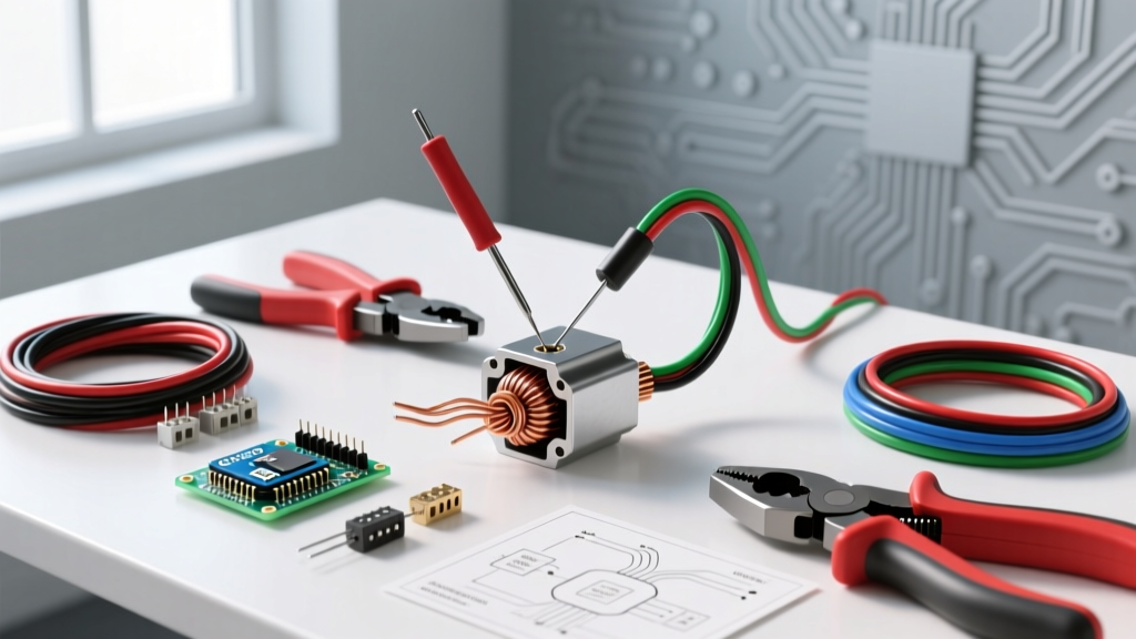

The Physical Layer: Why Stepper Motor Arduino Wiring Fails
When building CNC routers, 3D printers, or automated camera sliders, the microcontroller logic is only half the battle. The physical layer—specifically your stepper motor Arduino wiring—dictates long-term reliability. In 2026, with the dominance of ultra-quiet, high-microstepping drivers like the Trinamic TMC2209 and TMC5160, electromagnetic interference (EMI) and voltage drops are unforgiving. A poorly crimped Dupont connector or an untwisted wire pair will result in missed steps, layer shifts, or catastrophic thermal runaway.
This material and tool guide provides the exact specifications, wire gauges, and crimping protocols required to build industrial-grade wiring harnesses for Arduino-based stepper systems. We will bypass generic advice and focus on the specific components used by professional automation engineers.
Wire Selection: AWG, Stranding, and Shielding
The most common mistake in DIY electronics is using solid-core jumper wires for stepper motors. Stepper motors draw high, fluctuating currents that generate significant back-EMF. Solid-core wires will quickly work-harden and snap when subjected to the continuous vibration of a moving gantry. You must use stranded copper wire.
AWG Sizing by Motor Class
Selecting the correct American Wire Gauge (AWG) is critical to prevent voltage drop, which directly reduces the torque curve at higher RPMs. According to Adafruit's motor selection guide, matching wire thickness to the driver's maximum current output is essential for thermal management.
| Motor Size | Typical Phase Current | Minimum AWG | Recommended AWG (Long Runs >1m) |
|---|---|---|---|
| NEMA 14 / 17 | 0.8A - 1.5A | 22 AWG | 20 AWG |
| NEMA 23 | 2.0A - 3.5A | 18 AWG | 16 AWG |
| NEMA 34 | 4.0A - 6.0A+ | 14 AWG | 12 AWG |
The Case for Shielded Twisted Pair (STP)
Modern stepper drivers use high-frequency PWM (Pulse Width Modulation) to regulate current. This generates massive amounts of high-frequency EMI. If your stepper wires run parallel to sensitive Arduino sensor lines (like endstops or thermistors), the EMI will induce phantom voltages, causing the Arduino to register false triggers.
Pro-Tip: Always route stepper motor cables at a 90-degree angle to low-voltage signal cables. If parallel routing is unavoidable, use 4-core shielded cable (such as Belden 8723 or IGUS chainflex CF130) and ground the shield at the controller side only to prevent ground loops.
Connectors: Moving Beyond Dupont
Dupont connectors (the standard 2.54mm pitch black plastic headers) are designed for breadboarding and low-current signal logic. They are not rated for the continuous 1.5A+ loads typical of stepper motors. Under heavy load, Dupont contacts exhibit high resistance, leading to localized melting and intermittent connection failures.
Recommended Connector Ecosystems
- JST XH Series (2.54mm pitch): The standard for RAMPS and CNC shields. Rated for 2A to 3A per pin. Features a positive locking tab that prevents vibration-induced disconnects. Ideal for NEMA 17 setups.
- Molex Micro-Fit 3.0 (3.0mm pitch): The gold standard for NEMA 23 and NEMA 34 motors. Rated up to 5A per circuit. The robust housing and thick crimp tabs ensure zero voltage drop even at peak holding currents.
- Ferrules for Screw Terminals: If your driver board (like a DM542T or GeckoDrive) uses screw terminals, never insert bare stranded wire directly into the terminal block. The screw will fray the strands, reducing contact area. Always use crimped bootlace ferrules.
Essential Tools for Harness Building
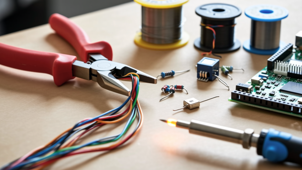
Building reliable harnesses requires precision tools. In 2026, the market is flooded with cheap clones, but investing in purpose-built crimpers saves hours of troubleshooting. Expect to spend roughly $80-$120 for a professional-grade bench setup.
1. Precision Wire Strippers
Do not use standard pliers. You need flush-cutting strippers that do not nick the copper strands. The Hakko CHP 170 or the Engineer PA-09 are industry favorites. Nicked strands create stress risers that will snap under vibration.
2. Ratcheting Crimpers
A ratcheting crimper ensures the terminal is compressed to the exact factory specification, preventing under-crimping (which pulls out) or over-crimping (which crushes the wire).
- For JST XH / Dupont: The IWISS SN-28B or Engineer PA-09 (approx. $25-$30). The ratchet mechanism guarantees a gas-tight connection.
- For Molex Micro-Fit: The IWISS SN-01BM or the official Molex 63811-1000 hand tool (expensive, but necessary for high-volume production).
- For Ferrules: The Glarks SN-48B or IWISS IWS-3220M (approx. $20-$25) provides the perfect quadrilateral or hexagonal crush for screw terminals.
Step-by-Step Harness Assembly Protocol
As documented in the RepRap wiki's stepper wiring documentation, the physical arrangement of the wires inside the harness is just as critical as the electrical connection. Stepper motors operate on two distinct phases (Coil A and Coil B).
Step 1: Identify and Twist the Pairs
Use a multimeter to identify the coil pairs. You will find continuity between A1 and A2, and between B1 and B2. Crucial Step: You must twist the wires of each pair together (e.g., twist A1 with A2, and B1 with B2). Twisting the pairs ensures that the magnetic fields generated by the forward and return currents cancel each other out, drastically reducing inductive crosstalk and EMI emissions. Aim for 2 to 3 twists per inch.
Step 2: Crimping and Tensile Testing
- Strip exactly 2.5mm of insulation from the stranded wire.
- Insert the bare copper into the terminal barrel, ensuring no stray strands escape.
- Place the terminal into the correct die of the ratcheting crimper and squeeze until the ratchet releases.
- The Tug Test: Pull the wire firmly by hand. A properly crimped 22 AWG wire should withstand over 15 lbs of tensile force without slipping. If it pulls out, adjust your crimper's ratchet tension dial.
Step 3: Strain Relief and Sleeving
Once the connectors are housed, apply 3M electrical tape or heat-shrink tubing at the back of the connector housing to provide strain relief. Finally, route the cables through PET expandable braided sleeving. This protects the insulation from abrasion against aluminum extrusions and moving gantry plates.
Common Failure Modes and Troubleshooting
Even with perfect code, physical wiring flaws will manifest as erratic behavior. Consult Pololu's stepper motor driver guide for driver-specific fault indications, but keep these physical failure modes in mind:
1. Motor Vibrates but Does Not Turn
Cause: One of the four wires is disconnected, or the coil pairs are mixed up (e.g., A1 is connected to B1). Fix: Verify continuity from the motor side to the Arduino driver side. Ensure A+ and A- are on the correct driver pins (usually labeled 1A, 1B, 2A, 2B). Do not rely solely on wire color codes; manufacturers frequently change color mappings without updating datasheets.
2. Random Arduino Resets During Motion
Cause: EMI from unshielded stepper wires is coupling into the Arduino's 5V logic rail or reset pin. Fix: Add a 100µF electrolytic capacitor directly across the VCC and GND pins on the stepper driver carrier board to smooth voltage spikes. Ensure your stepper cables are not zip-tied directly to the Arduino's USB cable or endstop signal wires.
3. Driver Overheating and Thermal Shutdown
Cause: Voltage drop due to undersized wire gauge or long cable runs, forcing the driver to work harder to maintain current regulation. Fix: Upgrade from 22 AWG to 18 AWG wire, or increase the power supply voltage (within the driver's absolute maximum rating, typically 35V for DRV8825 and 29V for TMC2209) to give the driver more headroom for PWM current shaping.
Final Thoughts on Harness Longevity
Treating your stepper motor Arduino wiring as a permanent, industrial harness rather than a temporary breadboard experiment is the hallmark of a mature DIY engineer. By investing in proper stranded cabling, ratcheting crimpers, and locking connectors, you eliminate the physical variables that cause 90% of all microcontroller project failures. Build it right the first time, and your machine will run flawlessly for years to come.