
The Hidden Dangers of Incorrect Choke Wiring
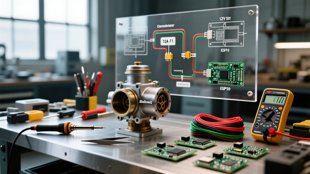
When upgrading to an Edelbrock Performer Series carburetor, such as the ubiquitous #1406 or #1411, the electric choke is a critical component for reliable cold-start enrichment. The choke cap houses a bi-metallic spring and a Positive Temperature Coefficient (PTC) ceramic heating element. When 12 volts are applied, the element heats up, expanding the spring and gradually opening the choke blade to prevent the engine from running overly rich as it warms. However, improper electric choke wiring Edelbrock setups remain a leading cause of under-hood electrical fires, melted wiring harnesses, and severe drivability issues in classic car restomods and daily drivers alike.
According to data from the National Fire Protection Association (NFPA), electrical failures and short circuits are among the primary culprits in vehicle fires. Because the engine bay is a high-heat, high-vibration environment with flammable fluids, every 12V circuit must be treated with rigorous safety standards. This guide details the exact engineering best practices, wire gauges, and relay configurations required to wire your Edelbrock electric choke safely and effectively.
The Ignition Coil Trap: Why It Is a Severe Fire Hazard
The most common—and most dangerous—mistake DIYers make is wiring the electric choke directly to the positive terminal of the ignition coil. While this seems logical because the coil only receives power when the ignition is in the "Run" or "Start" position, it violates fundamental electrical safety principles for two major reasons:
1. Circuit Overload and Inrush Current
When the Edelbrock choke is completely cold, the PTC heater exhibits low resistance and draws an inrush current of approximately 7 to 9 amps. As the cap heats up, resistance increases and the draw tapers down to a steady 1.5 amps. Most classic vehicle ignition circuits are wired with 16 AWG or 18 AWG wire and protected by a fuse or breaker rated for only 3 to 5 amps (designed solely for the coil's primary winding). Adding a 9-amp cold load to this circuit will instantly overload the wiring, potentially melting the insulation inside the dash or firewall before the factory fuse blows.
2. Voltage Drop and Choke Starvation
Classic vehicles equipped with points-style ignitions utilize a ballast resistor or a resistance wire to drop the voltage to the coil down to roughly 9V during normal running conditions. If you wire your choke to the coil, it will only receive 9V. The Edelbrock choke heater is calibrated to operate optimally at a full 12V to 14V. Starving it of voltage means the bi-metallic spring will never fully expand, leaving the choke blade partially closed. This results in a perpetually rich air/fuel mixture, fouled spark plugs, washed cylinder walls, and terrible fuel economy.
Selecting the Proper 12V Switched Source
To ensure safe electric choke wiring Edelbrock installations, you must source your power from a dedicated 12V switched circuit that is active only in the "Run" position. Do not use an "Accessory" circuit, as these often turn off when the key is bumped to the "Start" position, which will cause the choke to reset and close while you are cranking a cold engine.
- Fuse Box Auxiliary Terminals: Many modernized fuse panels (like those from Painless Performance or Centech) feature dedicated auxiliary switched terminals. These are ideal, provided they are fused correctly.
- Ignition Switch "IGN" Terminal: If running a new wire through the firewall, connect it to the "IGN" post on the back of the ignition switch, ensuring you install an inline fuse within 6 inches of the connection point.
- Wiper Motor or Heater Fan Switched Feed: In older classic cars lacking auxiliary fuse slots, tapping into the switched 12V feed for the wiper motor or heater blower (using a proper solder-seal splice connector, never a cheap scotch-lock) is a viable alternative, provided the existing circuit has the amperage headroom.
Wire Gauge, Routing, and Termination Standards
Using the correct wire gauge is non-negotiable. The high under-hood temperatures (often exceeding 200°F near the intake manifold) increase electrical resistance. You must use automotive-grade cross-linked polyethylene (XLPE) wire, such as GXL or TXL, which features thin, high-temperature insulation resistant to oil and heat.
| Wire Gauge (AWG) | Max Length (One Way) | Recommended Inline Fuse | Typical Application |
|---|---|---|---|
| 16 AWG | 4 Feet | 7.5A ATO | Short runs directly from a nearby relay |
| 14 AWG | 10 Feet | 10A ATO | Standard firewall-to-carburetor routing |
| 12 AWG | 16 Feet | 15A ATO | Long runs from front-mounted fuse boxes |
Termination Best Practice: Never use cheap vinyl electrical tape to seal your connections. Vinyl tape unspells in high heat and traps moisture, leading to galvanic corrosion. Always use adhesive-lined polyolefin heat shrink tubing. When heated, the inner lining melts and seals the wire strands completely against moisture and oxygen.
The Ultimate Safety Upgrade: Bosch-Style Relay Wiring
For the absolute highest standard of safety in 2026, especially on vehicles with high-output alternators or complex CAN-bus systems, you should not run the choke's full amperage through the firewall and ignition switch. Instead, use a standard Bosch-style 4-pin relay to handle the heavy lifting. As of 2026, a high-quality weather-sealed relay kit costs between $15 and $25 and provides immense peace of mind.
Step-by-Step Relay Configuration
- Pin 30 (Power In): Run a 12 AWG wire directly from the positive battery terminal or the main alternator output stud. Install a 15A inline Maxi or ATO fuse within 6 inches of the power source.
- Pin 87 (Power Out): Run a 14 AWG wire from this pin directly to the positive terminal on the Edelbrock choke cap.
- Pin 86 (Switched Trigger): Connect a lightweight 18 AWG wire to a low-amperage 12V switched ignition source. This only needs to carry the relay coil's tiny draw (less than 0.2 amps), completely eliminating voltage drop and fire risks to your ignition switch.
- Pin 85 (Ground): Secure this pin to a clean, unpainted metal surface on the engine block or intake manifold using a ring terminal and a star washer to bite through any corrosion.
"Utilizing a relay isolates the high-current choke heater from the vehicle's delicate factory wiring harness. It guarantees the choke receives a full, unimpeded 14.2 volts from the alternator, ensuring the fastest, most consistent warm-up cycle possible."
Proper Grounding Techniques for Edelbrock Chokes
The Edelbrock choke cap features two terminals. While one is for 12V power, the other is for ground. Many installers assume the carburetor body will automatically provide a sufficient ground path back to the battery. This is a critical error.
Modern intake manifold gaskets often feature rubber or composite coatings that act as electrical insulators. Furthermore, throttle linkages and pivot balls introduce multiple points of high electrical resistance. If the choke cannot find a solid ground, it will operate erratically or fail to open entirely. Always run a dedicated 14 AWG ground wire from the negative terminal on the choke cap directly to a verified, clean ground stud on the engine block or cylinder head.
Troubleshooting Common Failure Modes and Edge Cases
Even with meticulous wiring, environmental factors and component mismatches can cause issues. Here is how to diagnose the most common edge cases:
The Alternator Stator Trick (And Why to Avoid It)
In the 1970s, GM wired electric chokes to the alternator's "R" (stator) terminal, which only outputs voltage when the alternator is spinning. Some old-school mechanics still recommend this. Do not do this on modern vehicles. Modern high-output alternators can send AC ripple or unregulated voltage spikes through the stator terminal that will instantly melt the plastic choke cap. Always stick to a regulated, switched 12V DC source.
Melted Choke Caps and Overvoltage
If you find the black plastic cap on your Edelbrock #1406 is warped or melted, your charging system is likely overcharging. If your alternator's voltage regulator is failing and pushing 15.5V or higher, the PTC heater will overheat. Use a multimeter to verify your alternator output at idle; it should sit firmly between 13.8V and 14.4V.
Choke Opens Too Slowly
If the engine struggles to clear its throat after 3 to 5 minutes of driving, verify your voltage at the choke cap while the engine is running. If you measure less than 12V at the cap, you have excessive voltage drop in your wiring. Upgrade to a thicker wire gauge or switch to the relay method outlined above to eliminate the resistance.
Conclusion
Safe electric choke wiring Edelbrock carburetors requires moving beyond outdated "quick fixes" and embracing modern automotive electrical standards. By avoiding the ignition coil, selecting a dedicated switched 12V source, utilizing proper GXL wiring with adhesive-lined heat shrink, and implementing a Bosch-style relay, you guarantee reliable cold starts while completely eliminating the risk of an under-hood electrical fire. Treat your carburetor's electrical needs with the same respect you give your starter motor or ignition system, and your classic vehicle will reward you with flawless, weather-independent drivability.