
The Intersection of Smart Controls and Heavy-Duty Motors
When upgrading attic ventilation, installing agricultural exhaust systems, or integrating commercial HVAC components, wiring a relay for an electric fan is a critical step that bridges low-voltage smart controls with high-amperage motor loads. While a smart thermostat or a 24V humidistat can easily dictate when a fan should run, these delicate control devices cannot handle the inductive inrush currents of a 1/2 HP or 1 HP electric motor. This is where the relay—or more accurately in motor applications, the contactor—steps in.
However, treating an electric fan motor like a standard resistive lighting load is one of the most common and dangerous mistakes in electrical wiring. The National Electrical Code (NEC) has strict, highly specific mandates for motor circuits. This guide breaks down the exact code requirements, component sizing, and wiring procedures for safely integrating a relay into an electric fan circuit in 2026.
Terminology Check: Relay vs. Contactor
While often used interchangeably by DIYers, electricians differentiate the two. A relay typically handles control circuits or light resistive loads (under 15A). A contactor is a heavy-duty relay specifically engineered to make and break high-amperage inductive motor loads, featuring arc chutes and robust contact springs to prevent welding. For any fan motor exceeding 1/3 HP, you must use a motor-rated contactor, not a standard lighting relay.
NEC Article 430: The Core Standard for Fan Motor Circuits
General branch circuit rules (NEC Article 210) do not apply to electric fan motors. Instead, you must follow NEC Article 430, which governs motors, motor circuits, and controllers. When wiring a relay/contactor for an electric fan, three specific NEC sections dictate your installation:
1. Branch Circuit Sizing (NEC 430.22)
Electric fan motors draw significantly more current during startup (Locked Rotor Amps, or LRA) than during continuous operation (Full Load Amps, or FLA). To prevent nuisance tripping and conductor overheating, NEC 430.22 requires that branch circuit conductors supplying a single motor be sized at no less than 125% of the motor's Full Load Current (FLC).
2. Disconnecting Means (NEC 430.102)
You cannot rely solely on the relay or a remote smart switch to isolate the fan for maintenance. A local, lockable disconnect switch must be installed within sight of the fan motor. Furthermore, per NEC 430.83, this disconnect must be rated in Horsepower (HP), not just amps, to ensure it can safely interrupt the magnetic field of an inductive load without sustaining internal arc damage.
3. Overload Protection (NEC 430.32)
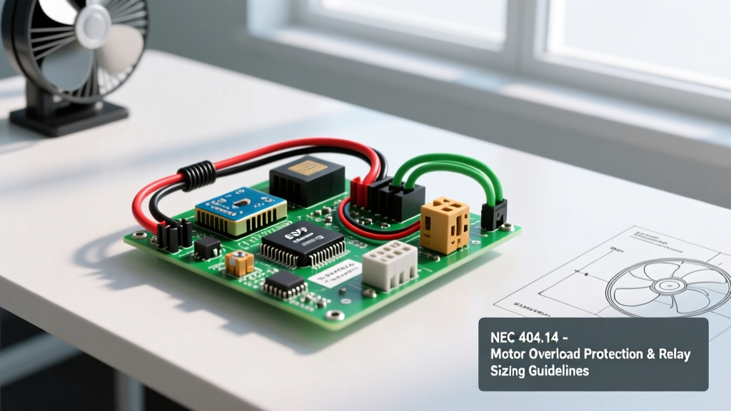
The relay itself does not provide thermal overload protection for the fan motor. If the fan blades become obstructed, the motor will overheat and catch fire. Overload protection (typically set between 115% and 125% of the motor nameplate FLA) must be provided either integrally within the fan motor (thermal auto-reset switches) or via an external overload relay block wired in series with the contactor.
Contactor Sizing Matrix for Common Electric Fans
Selecting the correct contactor requires matching the device's HP rating and FLA capacity to your specific fan. Below is a sizing matrix based on standard 2026 market availability for single-phase AC exhaust and attic fans.
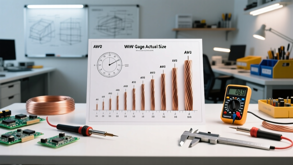
| Motor Size (HP) | Approx. FLA (120V / 240V) | Min. Contactor Rating | Min. Copper Wire Size (THHN) | Recommended Contactor Model |
|---|---|---|---|---|
| 1/4 HP | 5.8A / 2.9A | 15A (HP Rated) | 14 AWG | Honeywell R8222D1006 (Heavy Duty Relay) |
| 1/2 HP | 9.8A / 4.9A | 20A (HP Rated) | 12 AWG | Dayton 1EJW9 (30A Definite Purpose) |
| 1 HP | 16.0A / 8.0A | 30A (HP Rated) | 10 AWG | Schneider TeSys LC1D09 |
| 1.5 HP | 20.0A / 10.0A | 40A (HP Rated) | 10 AWG | Eaton C25DNF230B |
Note: Always verify the exact Full Load Amps (FLA) on the physical nameplate of your specific fan motor, as efficiency variations in modern ECM (Electronically Commutated Motor) models can alter these baselines.
Step-by-Step Code-Compliant Wiring Procedure
Follow this exact sequence to ensure your installation passes inspection and operates reliably for years.
- Install the Local Disconnect: Mount a NEMA 3R (outdoor/wet location) or NEMA 1 (indoor) HP-rated disconnect switch within 50 feet and in the direct line of sight of the electric fan. Pull your main branch circuit conductors from the breaker panel to this disconnect.
- Mount the Contactor Enclosure: Mount a NEMA-rated junction box near the fan (or inside the attic space) to house the contactor. Never leave a contactor exposed to insulation, dust, or moisture, as debris can jam the mechanical armature, causing the contacts to arc and weld shut.
- Wire the Load Side (High Voltage): Run conductors from the load side of the local disconnect to the Line (L1/L2) terminals of the contactor. Connect the fan motor leads to the Load (T1/T2) terminals of the contactor. Ensure all screw terminals are torqued to the manufacturer's specifications using a calibrated inch-pound screwdriver to prevent high-resistance hot spots.
- Wire the Control Circuit (Low Voltage): Wire your thermostat, humidistat, or smart relay output to the contactor's coil terminals (A1 and A2). If using a 24VAC control circuit, ensure you have a properly sized Class 2 transformer (e.g., 40VA minimum to handle the initial coil inrush current).
- Verify Overload Protection: If your fan motor does not have an internal thermal overload switch (check the nameplate for 'Thermally Protected'), you must wire an external bimetallic overload relay in series with the T1 or T2 load conductor.
Control Circuit Voltage Drop: The Hidden Failure Point
When wiring the low-voltage control side of the relay to a remote thermostat, voltage drop is a frequent cause of contactor failure. A standard 24VAC contactor coil requires at least 19.2V to pull the armature in completely. If the voltage drops below this threshold due to long runs of undersized thermostat wire, the contactor will 'chatter' or fail to close fully.
This partial closure creates a high-resistance air gap between the contacts, leading to extreme heat, pitting, and eventual contact welding. If your thermostat is located more than 75 feet from the fan contactor, upgrade your control wiring from standard 18 AWG bell wire to 16 AWG or 14 AWG stranded copper to mitigate voltage drop.
Common Code Violations and Edge Cases to Avoid
- The 'Lighting Relay' Trap: Using a standard 15A solid-state relay or lighting contactor (like those designed for LED banks) to switch an inductive fan motor. The inrush current of a motor will instantly destroy the triac or pit the mechanical contacts of a non-HP-rated relay.
- Missing Equipment Grounding: The metal enclosure housing the contactor, as well as the fan motor casing, must be bonded to the branch circuit equipment grounding conductor (EGC) per OSHA and NEC grounding mandates. A floating ground on a remote attic fan is a severe shock hazard.
- Smart Switch Overload: Wiring a smart Wi-Fi switch (rated for 15A resistive) directly in series with a 1/2 HP fan motor without an intermediary contactor. The smart switch's internal mechanical relay will fail within weeks due to inductive arcing.
Summary of Best Practices
Successfully wiring a relay for an electric fan requires respecting the physics of inductive loads and the legal mandates of the NEC. By sizing your conductors at 125% of the FLA, utilizing an HP-rated local disconnect, and selecting a definite-purpose motor contactor rather than a generic lighting relay, you ensure a system that is both legally compliant and mechanically bulletproof. Always consult the latest local amendments to the NEC, as regional jurisdictions may have specific requirements for attic and agricultural ventilation installations.