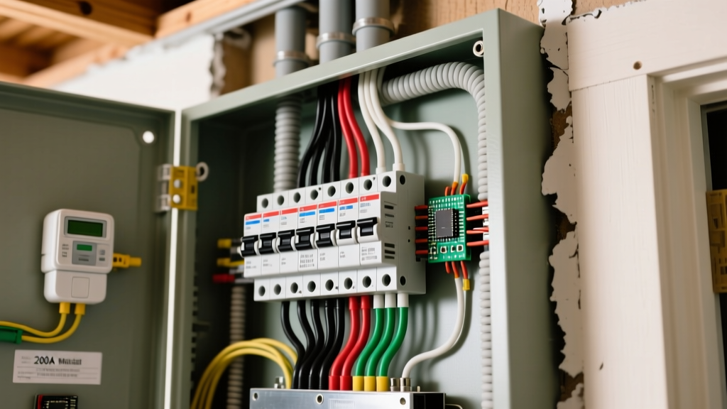
If you are stepping up from standard residential wiring into 3-phase workshop power, microgrids, or industrial control panels, you will eventually encounter the term resistance earthing (often called resistance grounding). In short, resistance earthing is the practice of inserting a calibrated resistor between the neutral point of a power source—like a transformer or generator—and the earth ground.
While a standard home panel relies on solid grounding to trip a breaker instantly during a fault, large 3-phase systems use resistance earthing to intentionally limit ground fault current. This prevents catastrophic equipment destruction and protects personnel from arc flash blasts. Here is exactly how it works, the specific hazards it mitigates, and where the boundaries lie between DIY shop work and licensed engineering.
The Hazard First: What Happens Without Current Limiting?
To understand why we intentionally add resistance to a ground path, you have to look at the physics of a solid ground fault on a high-capacity system.
Imagine a 480V, 3-phase industrial feed with a solidly grounded neutral. If a phase conductor faults to a grounded metal enclosure, the system sees a near-zero impedance path. The available fault current can easily exceed 40,000 amps. At this magnitude, two severe hazards emerge:
- Arc Flash and Magnetic Forces: The immense current generates magnetic forces strong enough to physically rip copper busbars out of their mounts. The heat vaporizes the metal, creating an explosive arc flash plasma that can reach 35,000°F—hotter than the surface of the sun. According to OSHA's arc flash guidelines, these events are a leading cause of severe electrical workplace injuries.
- Transient Overvoltages: If the fault isn't a solid bolted connection but an intermittent "arcing ground" (where the arc strikes, extinguishes, and restrikes), it can excite the system's natural capacitance. This restriking phenomenon can drive transient voltage spikes up to 6 to 8 times the nominal system voltage, instantly destroying motor insulation and sensitive VFDs (Variable Frequency Drives) on the same bus.
Ground, Bond, and Neutral: Clearing the Terminology
Before sizing or testing any earthing resistor, you must separate three concepts that are frequently conflated on the bench and in the field:
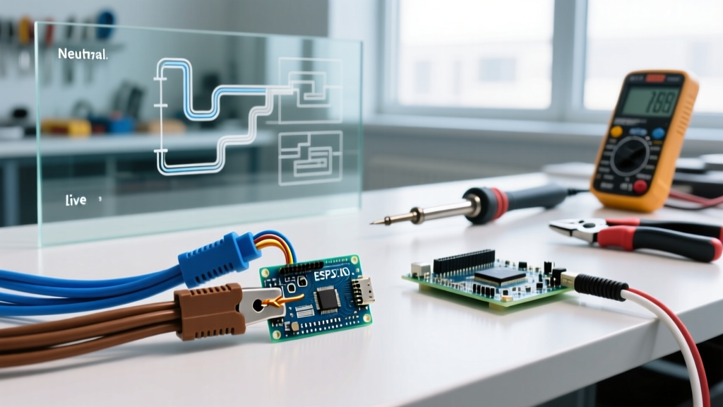
- Neutral: The intentional, current-carrying grounded conductor. In a 3-phase wye system, this is the physical center point where the three windings meet. It carries unbalanced load current under normal operation.
- Ground (Earthing): The non-current-carrying reference to the earth. Under normal conditions, zero current should flow through the earth ground path. It exists purely to stabilize system voltage to earth and provide a path for fault current.
- Bonding (Equipotential Bonding): The physical connection of all non-current-carrying metal parts (enclosures, conduit, machine frames) together. Bonding ensures that if a fault occurs, all metal surfaces rise to the same potential, preventing a shock hazard between two touchable surfaces.
In resistance earthing, the resistor is placed strictly between the neutral and the ground. The equipment bonding network remains a solid, zero-impedance copper path back to the source.
Decision Matrix: Solid vs. Resistance Earthing
Not every system needs an NGR. The choice depends on system voltage, capacity, and process criticality. Use this decision matrix to understand where each topology belongs.
| Grounding Topology | Typical Fault Current | Primary Hazard Prevented | Standard Application |
|---|---|---|---|
| Solid Grounding | Thousands of Amps (Unlimited) | Shock hazard (ensures rapid breaker trip) | Residential 120/240V, Light Commercial 208V/120V |
| Low-Resistance (LRG) | 200A – 400A | Arc flash damage, limits mechanical stress | Medium Voltage Industrial, Large 480V Motors |
| High-Resistance (HRG) | 5A – 10A | Transient overvoltages, allows continuous operation during a single fault | Critical Process Plants, Hospitals, Large Generators |
Note: Sizing an NGR requires calculating the system's capacitive charging current to ensure the resistive current is slightly higher than the capacitive current (for HRG), preventing resonance. This is governed by standards like IEEE C37.101 for generator grounding.
Verifying the Earthing Resistor and Safety Boundaries
If you are maintaining a 3-phase workshop subpanel or a backup generator equipped with an NGR, you need to verify the resistor hasn't degraded, cracked, or burned open. An open NGR effectively converts your system into an ungrounded system, bringing back the transient overvoltage hazard.
Here is the standard verification sequence. Note that while NFPA 70 (NEC) Article 250 provides the foundational framework for grounding and bonding, specific NGR installation and maintenance practices are often dictated by local AHJ (Authority Having Jurisdiction) and engineering standards. Always treat code references as guidance; your local inspector has final authority.
- De-Energize and LOTO: Shut down the transformer or generator. Apply Lockout/Tagout procedures. Verify the system is dead using a tested, rated voltage detector (e.g., Fluke 1587 or equivalent CAT IV meter). Never test an NGR on a live system.
- Visual Inspection: Open the NGR enclosure. Look for cracked porcelain insulators, carbon tracking (black soot paths), or melted stainless steel ribbon elements. Check that the neutral link and ground cable lugs are torqued to manufacturer specs and show no signs of thermal discoloration.
- Measure Resistance: Disconnect the NGR from the circuit to avoid parallel path errors. Use a Digital Low Resistance Ohmmeter (DLRO) for low-resistance units (which measure in milliohms or fractions of an ohm) or a standard multimeter/megohmmeter for high-resistance units (which may be 50 to 100 ohms). Compare the reading to the nameplate value. A variance of more than 5-10% usually indicates element degradation.
- Verify the Bypass Contactor (if applicable): Many HRG systems use a pulsing contactor that shorts out the resistor momentarily when a fault is detected, allowing standard overcurrent relays to trip the breaker. Verify the mechanical operation and coil voltage of this contactor.
Frequently Asked Questions About Resistance Earthing
Can I install resistance earthing on my home 240V split-phase panel?
No. Residential split-phase systems (120/240V) require solid grounding per NEC Article 250. The available fault current on a standard residential service is relatively low (typically 10,000A to 22,000A max), and standard residential breakers rely on high, unrestricted fault current to trip instantaneously and clear the fault before a fire starts. Adding resistance here would prevent your breakers from tripping, creating a massive fire and shock hazard.
What specific hazard does resistance earthing prevent in a 3-phase workshop?
In a large 3-phase workshop running 480V machinery, resistance earthing primarily prevents destructive arc flash blasts and transient overvoltages. By limiting a ground fault to, say, 400 amps (using a Low-Resistance Ground), the magnetic forces and thermal energy are kept low enough that the equipment enclosure survives the fault until the protective relays clear it, saving you from replacing a $50,000 motor control center.
How do I verify my resistance earthing system is functional?
You verify it by de-energizing the system, isolating the Neutral Grounding Resistor (NGR), and measuring its resistance with a DLRO or multimeter to ensure it matches the nameplate specification. You also perform a visual inspection for cracked insulators or burn marks. On live systems, specialized ground fault monitoring relays continuously verify the integrity of the neutral-to-ground path, but physical resistance testing must always be done de-energized.
When is a licensed electrical engineer or electrician required for resistance grounding?
A licensed professional is strictly required for the initial design, sizing, and installation of any NGR. Calculating the system's distributed capacitance to properly size a High-Resistance Ground, or coordinating the ground-fault relays with the main breaker trip curves on a Low-Resistance Ground, requires formal engineering. Furthermore, any physical connections at the service entrance or on medium-voltage (>600V) transformers legally require a licensed electrician in almost all jurisdictions.