
The Hidden 'Codes' of Low-Voltage Control Wiring
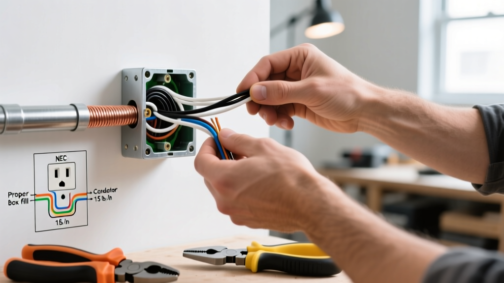
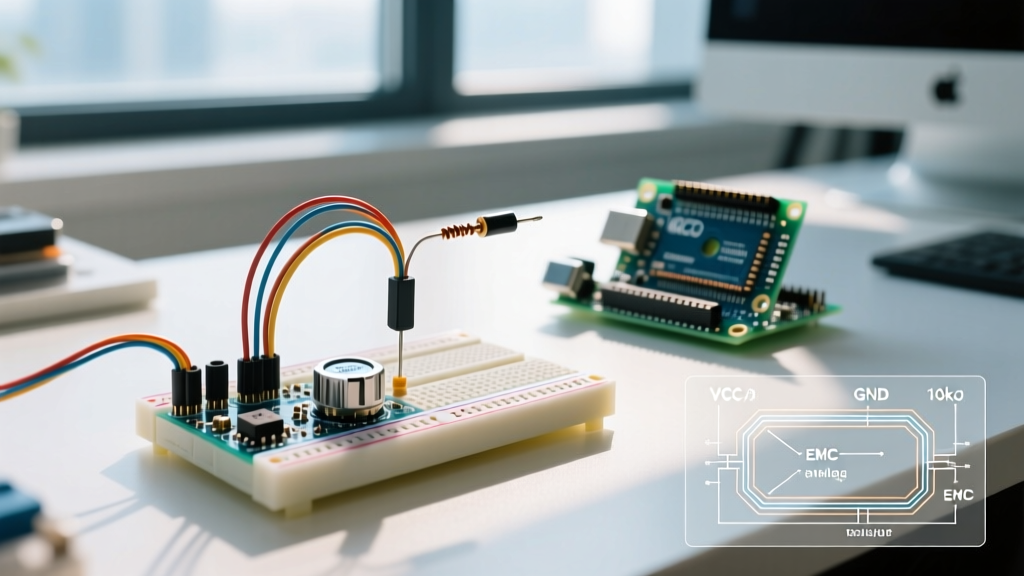
When electrical professionals think of wiring codes, the NEC (NFPA 70) Article 725 regarding Class 2 and Class 3 remote-control and signaling circuits usually comes to mind. However, when you zoom in from the wall conduit to the breadboard, potentiometer Arduino wiring is governed by an entirely different set of rigorous standards. While building inspectors won't check your microcontroller's breadboard, industrial OEMs, medical device manufacturers, and aerospace engineers rely on IEC (International Electrotechnical Commission) and IPC (Association Connecting Electronics Industries) standards to ensure signal integrity, electromagnetic compatibility (EMC), and long-term reliability.
In 2026, with the widespread adoption of high-resolution microcontrollers like the Arduino Uno R4 Minima (featuring a 14-bit ADC compared to the older R3's 10-bit ADC), the tolerance for noisy, non-compliant wiring has vanished. This guide translates high-level EMC and wire harness standards into actionable, code-compliant practices for your potentiometer Arduino wiring projects.
The Physics of Compliance: ADC Impedance Matching
Before discussing wire routing, we must address the most common failure mode in potentiometer Arduino wiring: ADC (Analog-to-Digital Converter) source impedance violation. A potentiometer is fundamentally a variable voltage divider. According to the official Arduino analogRead() documentation and the underlying ATmega/ARM Cortex-M4 datasheets, the ADC utilizes an internal sample-and-hold capacitor (typically around 14pF).
To charge this capacitor accurately within the 1.5 ADC clock cycles allocated for sampling, the source impedance must be 10 kΩ or less.
Expert Insight: Many hobbyists use a standard 100 kΩ Bourns or Alpha potentiometer to save power. When wired to an Arduino analog pin, the high impedance prevents the internal capacitor from fully charging, resulting in non-linear readings, severe jitter, and cross-talk from adjacent analog pins. Always select a 5 kΩ or 10 kΩ linear taper (B-Taper) precision potentiometer, such as the Bourns 3590S series, for direct microcontroller wiring.
IEC 61000-6-2: EMC Immunity in Potentiometer Circuits
If your Arduino project operates in an environment with motors, relays, or switching power supplies, your wiring must theoretically comply with IEC 61000-6-2 (Immunity for Industrial Environments). Potentiometer wipers output a high-impedance analog signal, making the connecting wires act as highly efficient antennas for Electromagnetic Interference (EMI).
Routing and Shielding Standards
- Trace/Wire Length: Keep the physical wire run between the potentiometer wiper and the Arduino analog pin under 3 inches (7.5 cm). Beyond this length, the wire's inductance and capacitance degrade the signal and increase EMI susceptibility.
- Shielding: For runs exceeding 3 inches, abandon standard jumper wires. Use a shielded twisted-pair (STP) cable. The shield must be tied to the Arduino's ground (GND) at one end only to prevent ground loops, a strict requirement in industrial EMC design.
- Separation Distances: Never route low-voltage analog sensor wires parallel to AC mains or high-current DC motor lines. Maintain a minimum 2-inch (50 mm) separation, or cross them at a strict 90-degree angle.
IPC/WHMA-A-620: Wire Harness and Termination Standards
Shoving bare, stripped wire into an Arduino's female header or soldering directly to the PCB is a violation of IPC/WHMA-A-620 (Requirements and Acceptance for Cable and Wire Harness Assemblies). For a reliable, production-grade connection, terminations must withstand mechanical pull forces and resist oxidation.
Wire Selection and Termination Matrix
| Application Context | Wire Specification | Termination Method | IPC Class Target |
|---|---|---|---|
| Prototyping / Bench Testing | 24 AWG Stranded (PVC) | Pre-crimped Dupont-style (0.1" pitch) | Class 1 (General) |
| Industrial Control Panel | 22 AWG Stranded (PTFE/XLPE) | Ferrule + Spring-clamp terminal block | Class 2 (Dedicated) |
| High-Vibration / Aerospace | 24 AWG Mil-Spec (M16878) | Solder-cup + Heat-shrink strain relief | Class 3 (High Performance) |
Step-by-Step: Code-Compliant Potentiometer Arduino Wiring
Follow this procedure to build a robust, standards-compliant harness for a precision 10 kΩ panel-mount potentiometer connected to an Arduino Uno R4.
- Component Preparation: Mount the Bourns 3590S-1-103L (10 kΩ, 10-turn precision pot) to your enclosure. Cut three lengths of 24 AWG stranded wire (red for 5V, black for GND, yellow for Wiper).
- Stripping and Ferrule Crimping: Strip exactly 5mm of insulation from the pot-side wires. Crimp 0.25mm² uninsulated bootlace ferrules onto the ends. This prevents wire fraying and ensures a gas-tight connection when soldered or screwed into lugs.
- Potentiometer Termination: Solder the ferrule ends to the potentiometer lugs. Use a temperature-controlled iron (e.g., Weller WE1010NA) set to 350°C with 63/37 Sn/Pb or SAC305 lead-free rosin-core flux. Apply heat for no more than 3 seconds to prevent thermal damage to the pot's internal resistive track.
- Microcontroller Termination: On the Arduino side, crimp the wires using TE Connectivity AMP MCP 2.8mm contacts or high-quality 0.1" pitch pre-crimped housings (like Molex KK 254). Insert into the Arduino's female headers until the tactile 'click' is felt, ensuring the locking tab is engaged.
- Signal Conditioning (The RC Filter): To guarantee IEC-level noise immunity, solder a 100nF (0.1µF) X7R ceramic capacitor directly between the Wiper (yellow wire) and GND (black wire) at the Arduino header. This creates a low-pass filter that stabilizes the ADC reading by bleeding off high-frequency EMI spikes.
Power Supply Safety: UL 62368-1 Compliance
A frequently overlooked aspect of low-voltage wiring is the power source. If your Arduino and potentiometer circuit are powered by an external AC-to-DC wall adapter, that adapter must comply with UL 62368-1 (Audio/video, information and communication technology equipment safety standard). Using uncertified, ultra-cheap 5V switching power supplies can introduce severe 50/60Hz ripple and high-frequency switching noise directly into the Arduino's 5V rail, destroying your analog readings and posing a fire/shock hazard. Always source power supplies with verifiable UL/CE marks and low ripple specifications (< 30mV p-p).
Troubleshooting ADC Jitter: A Standards-Based Approach
Even with perfect wiring, environmental factors can cause analog readings to fluctuate. Use this diagnostic framework:
- Symptom: Reading jumps by ±10 to ±20 bits randomly.
Root Cause: High-frequency EMI coupling into the unshielded wiper wire.
Standard Fix: Verify the 100nF bypass capacitor is installed. If noise persists, add a 1kΩ series resistor between the wiper and the Arduino pin to form an active RC low-pass filter. - Symptom: Reading is non-linear; turning the pot halfway does not yield ~512 (on a 10-bit scale).
Root Cause: Source impedance exceeds 10 kΩ, or an audio-taper (A-Taper) pot was mistakenly used instead of a linear-taper (B-Taper).
Standard Fix: Replace with a verified linear 5kΩ or 10kΩ potentiometer. Buffer the signal using an LM358 op-amp configured as a unity-gain voltage follower if a high-resistance pot is strictly required. - Symptom: Analog values drift upward slowly over time.
Root Cause: Thermal drift in the potentiometer's resistive element or poor solder joints expanding under heat.
Standard Fix: Inspect IPC-A-620 solder joint quality. Ensure the potentiometer is rated for the ambient operating temperature (e.g., mil-spec pots rated for -55°C to +125°C).
Summary
Professional potentiometer Arduino wiring requires looking beyond basic electrical continuity. By respecting ADC impedance limits, applying IEC EMC routing principles, and executing IPC-compliant wire terminations, you transform a fragile breadboard prototype into a resilient, industrial-grade sensor interface. Whether you are building a custom MIDI controller or an industrial valve positioner, adherence to these standards ensures your microcontroller reads the physical world with absolute precision.