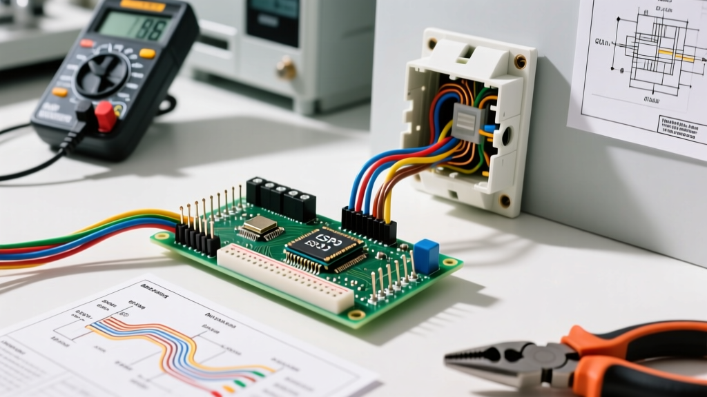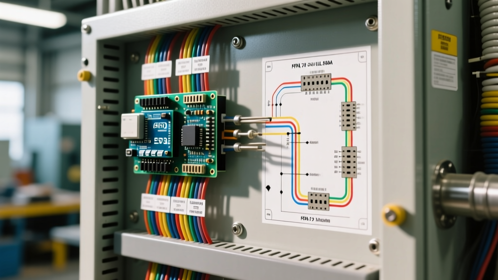

The High Stakes of Control Panel Compliance
When an Authority Having Jurisdiction (AHJ) steps onto a job site to inspect a newly installed industrial machine or motor control center, they are not just looking for neatness. They are verifying strict adherence to electrical control panel wiring standards to ensure human safety and fire prevention. Failing an inspection does not merely mean a slap on the wrist; it results in rejected commissioning, project delays costing thousands of dollars per day, and mandatory rework. In 2026, with supply chain lead times for replacement components still fluctuating, building a panel correctly the first time is a critical financial imperative.
To build panels that pass inspection flawlessly, electrical engineers and panel builders must synthesize requirements from three primary frameworks: the National Electrical Code (NEC / NFPA 70), UL 508A, and NFPA 79. Understanding how these standards interact—and where they diverge—is the hallmark of a master panel builder.
The Regulatory Triad: NEC, UL 508A, and NFPA 79
Inspectors use a hierarchy of standards depending on the application. While the NEC governs the facility and the power feed, UL 508A and NFPA 79 dictate the internal anatomy of the control panel itself. Below is a functional comparison of how these standards apply to your build.
| Standard | Primary Scope | Key Focus for Inspectors | SCCR Requirement |
|---|---|---|---|
| NEC (NFPA 70) Article 409 | Installation of industrial control panels in the field. | Wire sizing, overcurrent protection, disconnect means, and field wiring. | Requires SCCR marking on the panel exterior. |
| UL 508A | Construction of industrial control panels (general purpose). | Component spacing, short-circuit ratings, internal wire routing, and temperature limits. | Mandates calculation via Supplement SB or tested combinations. |
| NFPA 79 | Electrical equipment for industrial machinery. | Wire color coding, emergency stop circuits, and operator interface safety. | Aligns with UL 508A but adds machinery-specific interlock rules. |
For a comprehensive overview of facility-level requirements, always refer to the NFPA 70 National Electrical Code documentation. However, for the internal wiring of the panel, UL 508A and NFPA 79 will be your daily bibles.
NFPA 79 Wire Color Coding: The First Thing Inspectors Check
Before an inspector even opens a wire duct, they will look at the terminal blocks and component wiring. NFPA 79 (Section 13.2) establishes a strict color code for conductors. Deviating from these colors is an immediate red flag that suggests the panel was built by unqualified personnel.
- Black: AC power circuits (main power, motor feeds).
- Red: AC control circuits (typically 120VAC or 240VAC control logic).
- Blue: DC control circuits (typically 24VDC from a power supply to PLCs and sensors).
- Yellow: Interlock circuits wired from outside the control enclosure (power that remains live even when the main panel disconnect is off).
- White or Natural Gray: AC neutral or grounded DC circuits.
- Green with Yellow Stripe: Protective Earth (PE) ground. Note: Solid green is no longer permitted for PE in new NFPA 79 builds; it must be green/yellow.
Pro Tip: If you are mixing 120VAC control (Red) and 24VDC control (Blue) in the same wiring duct, ensure your wire markers clearly denote the voltage level at both ends of the conductor, as required by NEC 409.11.
Wire Routing, Bending Space, and Voltage Separation
Crossing high-voltage power lines with low-voltage signal wires induces electromagnetic interference (EMI) and creates a severe shock hazard if insulation fails. NEC 409.42 and UL 508A mandate physical separation.
The 90-Degree Crossing Rule
When power and signal wires must cross, they must do so at a strict 90-degree angle to minimize capacitive coupling and EMI. Never run 480VAC motor leads parallel to 24VDC Ethernet cables. If parallel routing is unavoidable, maintain a minimum separation distance based on voltage:
- Under 300V: Minimum 2 inches of separation or a grounded metal barrier.
- 300V to 600V: Minimum 4 inches of separation or a grounded metal barrier.
Wire Duct Sizing and Fill Capacity
Inspectors will physically remove the covers of your Panduit or Hoffman wire ducts to check fill capacity. UL 508A dictates that wiring ducts must not be filled beyond 50% of their cross-sectional area at any point. Using a UL 508A certified component list, builders often select ducts like the Panduit F2X2LG6 (2x2 inch) but fail to account for the wire bending radius at the duct exits. Always upsize your duct by one dimension if you are routing multiple 10 AWG or 8 AWG motor leads to prevent insulation crushing when the snap-on cover is applied.
Termination Integrity: Torque Specs and Ferrule Mandates
Loose connections cause high resistance, leading to localized heating, melted insulation, and eventual panel fires. In 2026, AHJs are increasingly using thermal imaging cameras during commissioning to spot hot spots caused by under-torqued terminals.
Specific Torque Values
You cannot rely on 'hand-tight' or 'gopher-tight' estimations. You must use a calibrated torque screwdriver (such as the CDI 401SM or Wihaha precision torque driver) set to the manufacturer's exact specifications. Typical values for standard screw-type terminal blocks and contactors include:
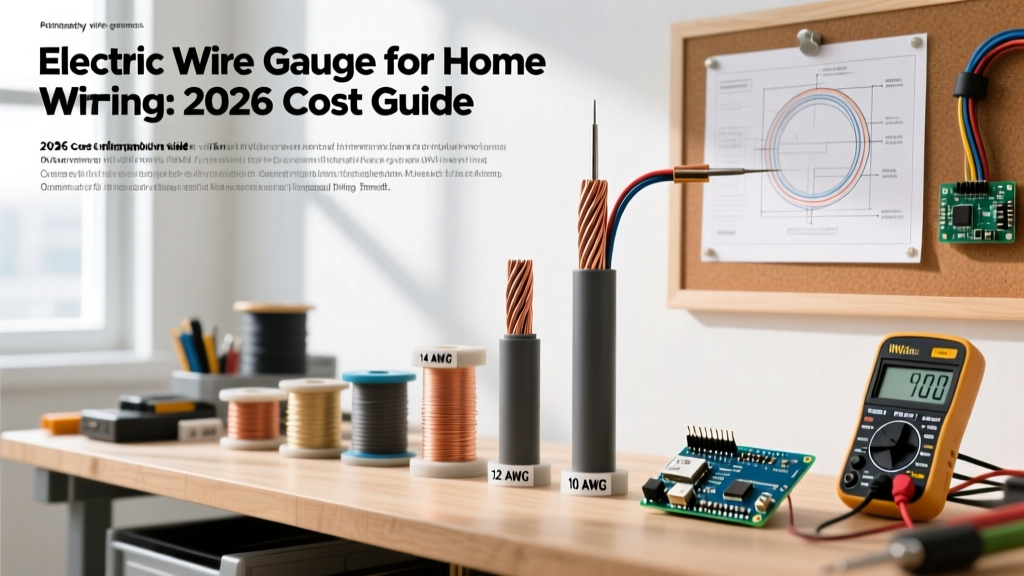
- 14 AWG (2.5 mm²): 12 to 14 in-lbs
- 12 AWG (4.0 mm²): 14 to 16 in-lbs
- 10 AWG (6.0 mm²): 15 to 18 in-lbs
- 8 AWG (10.0 mm²): 20 to 25 in-lbs
The Shift to Ferrules
While not strictly mandated by the NEC for all applications, UL 508A and modern best practices heavily favor the use of wire ferrules for stranded wire terminations. Tinning stranded wire with solder is explicitly prohibited by UL 508A because solder creeps under pressure, leading to loose connections over time. Instead, use DIN-standard ferrules. For example, when terminating 16 AWG wire into a Phoenix Contact or Weidmüller terminal block, use a Phoenix Contact AI 1,5 - 8 BK ferrule, crimped with a ratcheting ferrule crimper to ensure a gas-tight seal.
Top 4 Control Panel Inspection Failure Points
Based on field data and OSHA electrical safety guidelines, the following edge cases are the most common reasons panels are red-tagged during final inspection.
1. Missing or Miscalculated SCCR Labels
Every industrial control panel must bear a Short-Circuit Current Rating (SCCR) label on the outside of the enclosure. If your facility has 65kA of available fault current at the transformer, but your panel is only rated for 10kA, the panel will violently fail during a short circuit. Inspectors will ask for your SCCR calculation worksheet (usually based on UL 508A Supplement SB). If you cannot produce it, you fail.
2. Undersized Protective Earth (PE) Bus Bar
The internal ground bus bar must be sized to handle the maximum fault current the panel will endure, not just the nominal current. Furthermore, NEC 250.122 requires the equipment grounding conductor to be sized based on the main overcurrent protective device. A common failure is using a tiny 1/4-inch copper bus bar for a panel fed by a 400A main breaker. The bus must be physically robust enough to withstand the magnetic forces of a 65kA fault without tearing away from the standoffs.
3. Dead Front Violations
NEC 409.100 requires that panels be constructed so that no live parts are exposed to an operator when the enclosure door is open. If you have 120VAC or 480VAC terminal blocks mounted near the door swing, you must install a polycarbonate dead-front shield or use IP20 finger-safe terminal blocks (like the Wago TOPJOB S series). Inspectors will physically reach into the panel with a standard test probe to verify IP20 compliance.
4. Missing Wire Markers at Both Ends
Every wire must be permanently marked at both termination points with a designation that matches the electrical schematic. Wrap-around heat shrink or high-quality self-laminating vinyl markers (printed via a Brady BMP71 or similar thermal transfer printer) are required. Handwritten tape labels are an instant rejection in modern industrial environments.
Final Thoughts on Compliance
Adhering to electrical control panel wiring standards is not about doing the bare minimum to satisfy an inspector; it is about engineering a system that will operate safely for decades. By internalizing the color codes of NFPA 79, the separation rules of UL 508A, and the termination rigor demanded by the NEC, you transform your panel shop from a simple assembly line into a center of electrical excellence. Always keep your torque tools calibrated, your SCCR calculations documented, and your wire ducts below the 50% fill line.