
The Critical Role of Code in Electrical Distribution Panel Wiring
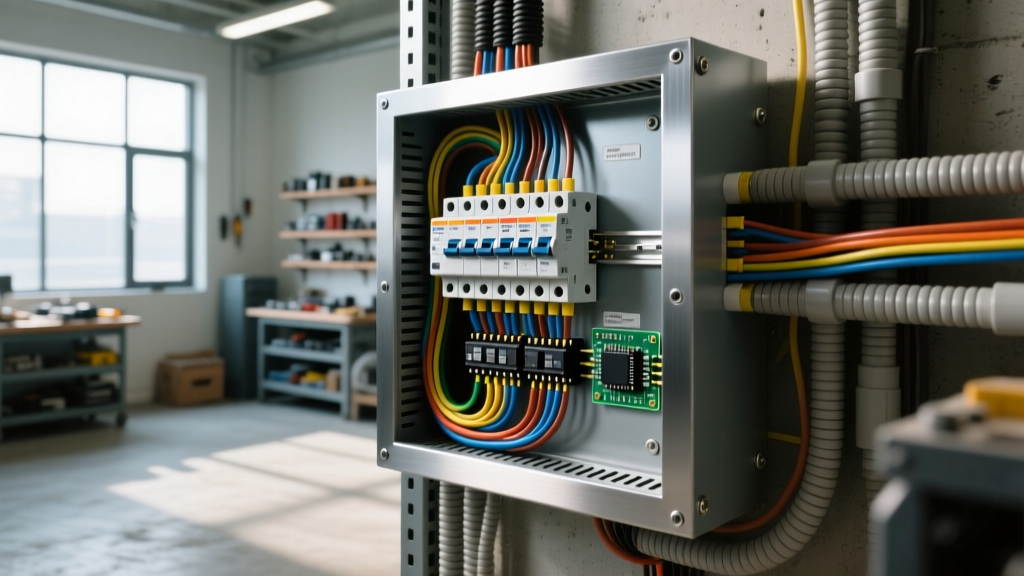
When it comes to commercial and residential power systems, electrical distribution panel wiring serves as the central nervous system of the building. While DIY enthusiasts and junior electricians often focus primarily on matching wire colors and ensuring circuits are live, master electricians and AHJs (Authorities Having Jurisdiction) focus on strict adherence to the National Electrical Code (NEC). As jurisdictions across the country continue to adopt the NEC 2023 and prepare for the 2026 code cycle updates, understanding the granular requirements for panelboards is no longer optional—it is a matter of life safety and fire prevention.
Improper electrical distribution panel wiring can lead to catastrophic arc flash events, thermal runaway at termination points, and neutral-to-ground fault loops. This guide breaks down the most critical NEC standards governing panelboard installations, moving beyond basic wiring diagrams to explore the exact measurements, torque specifications, and bonding rules that define a code-compliant installation.
Working Space and Clearance Requirements (NEC 110.26)
Before a single wire is stripped, the physical environment of the panel must meet strict clearance requirements. NEC Article 110.26 dictates the minimum working space around electrical equipment operating at 600 volts or less. Inspectors will immediately fail an installation if the electrical distribution panel wiring is performed in a space that violates these dimensions.
The 30-36-78 Rule
- Width: The working space must be at least 30 inches wide, or the width of the equipment itself, whichever is greater. This space does not need to be centered on the panel, but it must allow the panel door to open to at least 90 degrees.
- Depth: For standard residential and light commercial systems (0 to 150 volts to ground), the minimum clear depth is 36 inches. If the panel faces an exposed grounded conducting surface (like a metal stud wall), this depth increases to 42 inches for 151-600V systems.
- Height: The space must extend from the floor (or platform) up to 6.5 feet, or the height of the equipment, whichever is higher. This dedicated volume must remain completely clear of stored materials, plumbing, or HVAC ductwork.
Inspector's Note: NEC 240.24 explicitly prohibits locating overcurrent devices (panels) in the vicinity of easily ignitable materials, such as in clothes closets or bathrooms. While older homes may have grandfathered panels in these locations, any remodel or upgrade requires relocating the panel to a compliant, dedicated space.
Conductor Bending Space and Gutter Sizing (NEC 312.6)
One of the most frequent failure points in electrical distribution panel wiring is the physical overcrowding of conductors inside the panel gutter. When large-gauge wires are forced into tight spaces, the insulation can be damaged, or the wire may exert excessive mechanical stress on the breaker terminals. NEC 312.6 establishes minimum wire bending space based on the size of the conductor and the number of wires entering the cabinet per terminal.
Below is a simplified reference table based on NEC Table 312.6(A) for minimum bending space at terminals:
| Wire Size (AWG/kcmil) | 1 Wire per Terminal (Inches) | 2-5 Wires per Terminal (Inches) |
|---|---|---|
| 14 - 10 AWG | Not Specified (Standard Gutter) | Not Specified |
| 8 - 6 AWG | 1.5 | 2.0 |
| 4 - 3 AWG | 2.0 | 3.0 |
| 2 - 1 AWG | 3.0 | 4.0 |
| 1/0 - 2/0 AWG | 3.5 | 4.5 |
| 3/0 - 4/0 AWG | 4.0 | 6.0 |
| 250 - 350 kcmil | 5.0 | 8.0 |
When pulling large feeders into a panel, always use an NEC-approved wire pulling compound (such as Ideal 31-091) to reduce friction and prevent insulation scoring against the metal knockouts and cabinet edges.
Torque Specifications: The Silent Failure Point (NEC 110.14(D))
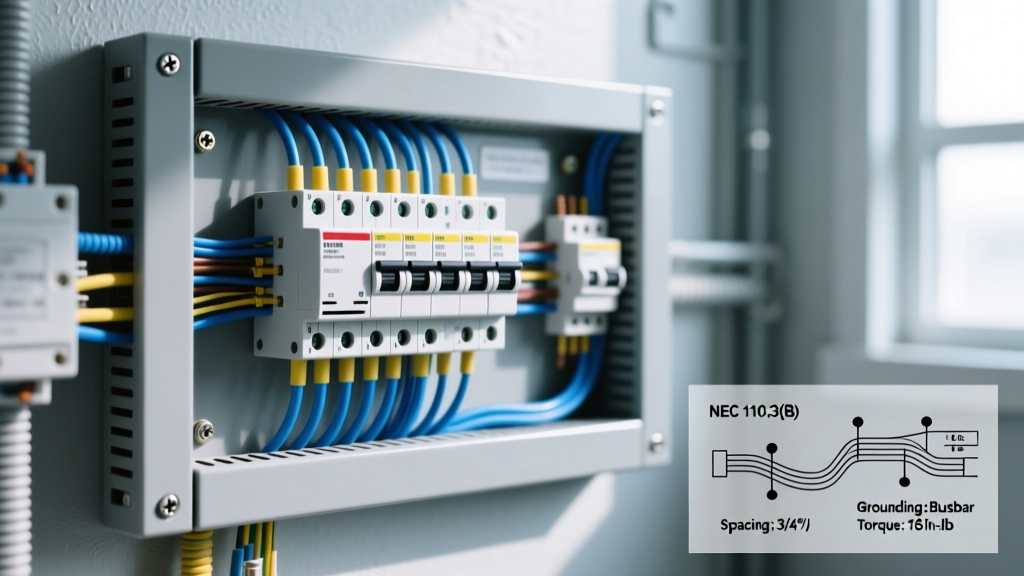
Historically, electricians relied on the 'tighten until it stops, then give it a quarter turn' method. This approach is now a direct code violation. NEC 110.14(D) mandates that all mechanical connections for electrical conductors must be torqued to the manufacturer's specified values using a calibrated tool. This rule was heavily expanded in the 2017 and 2020 codes and remains strictly enforced in 2026.
Under-torquing leads to loose connections, which increase electrical resistance and generate excessive heat. Over-torquing strips threads, deforms the wire strands (especially aluminum), and causes cold flow, eventually resulting in the exact same loose connection over time.
Standard Torque Values for Common Breakers
While you must always check the specific manufacturer's label on the breaker or panelboard dead-front, here are standard torque specifications for common residential and commercial breakers (e.g., Square D QO and Homeline series):
- 14 - 10 AWG (15A - 30A Breakers): 35 in-lbs (inch-pounds)
- 8 - 4 AWG (40A - 60A Breakers): 40 in-lbs
- 3 - 1/0 AWG (70A - 125A Breakers): 150 in-lbs
- Main Lugs (2/0 - 4/0 AWG): Typically 250 to 350 in-lbs (requires a heavy-duty torque wrench, such as the CDI 401SM or Klein 32500 series torque screwdriver).
Note: Always use an inch-pound torque screwdriver for branch circuits. Using a foot-pound wrench on a small terminal will instantly destroy the lug.
Grounding vs. Bonding in Subpanels (NEC 250.142 & 408.40)
The distinction between grounding and bonding is where many electrical distribution panel wiring projects fail inspection. The NEC is unequivocal: neutral (grounded conductor) and equipment ground (grounding conductor) must only be bonded together at the main service disconnecting means.
The Main Panel (Service Equipment)
At the main service panel, the neutral bar and the equipment grounding bar are bonded together, usually via a green main bonding screw or a copper bonding strap. This provides a low-impedance fault current path back to the utility transformer, allowing the main breaker to trip instantly during a ground fault.
The Subpanel (Downstream Distribution)
For any subpanel fed from the main panel, the neutral and ground must remain strictly isolated. According to NEC 408.40, the equipment grounding conductor must be routed with the feeder wires, and the panel must feature an isolated neutral bar. If the green bonding screw is left in place in a subpanel, normal neutral return current will travel back to the main panel via both the neutral wire and the bare copper ground wire. This energizes the grounding system, creating a severe shock hazard and potential electromagnetic interference on sensitive electronics.
Overcurrent Protection and Busbar Stab Limits (NEC 408.54)
When designing the electrical distribution panel wiring layout, you cannot simply fill every available slot with a breaker. NEC 408.54 addresses the maximum rating of overcurrent devices protecting the busbar.
In a standard main-breaker panel, the main breaker protects the busbar. However, in a main-lug-only (MLO) panel acting as service equipment, the sum of the ampere ratings of the individual branch circuit breakers cannot exceed the ampere rating of the busbar. Furthermore, physical busbar stab limits dictate that no more than two overcurrent devices can be connected to a single busbar stab (the physical metal prong that connects to the breaker). Attempting to use tandem/cheater breakers on a panelboard not explicitly rated and labeled for them (CTL vs. Non-CTL) is a severe violation that can cause the busbar to overheat and melt.
Common Code Violations to Avoid
To ensure your electrical distribution panel wiring passes inspection on the first attempt, avoid these frequent NEC violations cited by the International Association of Electrical Inspectors (IAEI):
- Double-Tapping Unrated Lugs: NEC 110.14(A) states that terminals must be used only for the number of conductors they are rated to accept. While some Square D and Eaton breakers allow two wires on a single terminal, they must be the same wire type and size, and the breaker must explicitly feature a pressure plate designed for two wires. If not, use a wire nut and a pigtail.
- Exposed Knockouts: NEC 314.42 requires that all unused cabinet openings be closed to provide protection substantially equivalent to the wall of the cabinet. Use metallic knockout seals; plastic plugs are often rejected in commercial settings due to fire-rating requirements.
- Improper Neutral Splicing: Neutrals must terminate individually on the neutral bar. Splicing two neutral wires together and landing them on a single neutral bar screw is a violation unless the lug is specifically rated for it.
- Missing Circuit Directory: NEC 408.4 requires a legible, permanent circuit directory that identifies the purpose of each breaker with a high degree of specificity. Vague labels like 'Living Room' or 'Receptacles' are routinely rejected; use 'Living Room South Wall Receptacles' instead.
For comprehensive safety standards regarding live work and arc flash boundaries during panel maintenance, always consult OSHA's electrical safety guidelines and NFPA 70E. Proper electrical distribution panel wiring is not just about making the circuit work; it is about ensuring the system remains safe, stable, and compliant for decades to come.