The Lethal Cost of Undersized Earthing
When a live 120V or 230V conductor faults to a metal appliance chassis, the earthing wire (Equipment Grounding Conductor) must carry a massive surge of fault current back to the panel. This surge is what forces the circuit breaker to trip in milliseconds. If your earthing size is too small, the wire cannot handle the thermal stress. It acts like an undersized fuse, melting or vaporizing before the breaker's magnetic trip engages.
Choosing the correct earthing size is not about matching the live wire; it is about ensuring the wire has enough cross-sectional area to survive the fault current long enough for the overcurrent protective device (OCPD) to clear the circuit. The following guidance is based on NEC-style principles (specifically Article 250) and IEC 60364 equivalents. Always treat this as technical guidance; your local Authority Having Jurisdiction (AHJ) or licensed inspector has final legal authority over code compliance.
Ground, Neutral, and Bond: Clearing the Confusion
Before sizing conductors, you must understand the distinct roles of the wires in your panel. Confusing these leads to dangerous wiring errors.
- Neutral (Grounded Conductor): The normal return path for current in a single-phase circuit. It carries the exact same current as the live wire during normal operation. It is insulated (white or grey) and bonded to ground only at the main service disconnect.
- Earth/Ground (Equipment Grounding Conductor): A safety path that carries zero current during normal operation. It only carries current during a fault. It is bare or green-insulated and connects to all non-current-carrying metal parts (chassis, conduit, boxes).
- Bonding: The physical, intentional connection between the neutral bar and the ground bar. In a main panel, the main bonding jumper ties them together, establishing a zero-reference potential. In a subpanel, this bond must be removed to prevent neutral current from flowing on the ground wire.
The earthing size dictates the capacity of that emergency fault path. For a deep dive into the physics of these pathways, the National Fire Protection Association (NFPA) maintains the foundational standards for grounding and bonding.
Earthing Size Decision Matrix
The minimum earthing size for branch circuits and feeders is dictated by the rating of the circuit breaker protecting it, not the size of the live conductors. Below is the standard matrix for copper conductors. If you are using aluminum, you must generally step up one AWG size.
| Breaker Rating (Amps) | Min Copper Earthing Size (AWG) | Min Copper Earthing Size (mm²) | Common Applications |
|---|---|---|---|
| 15A / 20A | 14 AWG | 2.5 mm² | General lighting, standard 120V receptacles |
| 30A | 10 AWG | 6.0 mm² | Dryers, water heaters, RV outlets |
| 40A / 50A | 10 AWG | 6.0 mm² | Electric ranges, EV Level 2 chargers (up to 40A continuous) |
| 60A | 10 AWG | 6.0 mm² | Subpanel feeders, large HVAC condensing units |
| 100A | 8 AWG | 10.0 mm² | Large subpanels, heavy workshop equipment |
| 200A | 6 AWG | 16.0 mm² | Main residential service feeders |
The Voltage Drop Upsizing Rule
Here is a critical edge case that trips up many DIYers: If you have a long cable run (like a detached garage 150 feet away) and you must upsize your live wires from 8 AWG to 6 AWG to prevent voltage drop, you must proportionally upsize the earthing wire as well. According to NEC 250.122(B), if ungrounded conductors are increased in size, equipment grounding conductors must be increased proportionately based on the circular mil area. You cannot run 6 AWG live wires with a 10 AWG ground just because the breaker is 60A; the ground must scale up to maintain the same impedance ratio.
Verifying Your Earth Path with a Tester
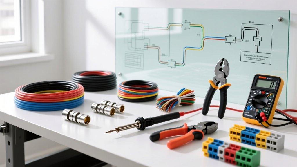
Running the wire is only half the job; verifying the path has low impedance is what actually ensures safety. A standard $10 plug-in receptacle tester only checks for the presence of a ground wire, not its capacity or integrity.
Step 1: Continuity Testing (De-energized)
With the circuit breaker OFF and verified dead, set your multimeter to the lowest ohms range. Place one probe on the appliance chassis or metal box and the other on a known good ground (like the panel's ground bar). You should read less than 1.0 ohm. If it reads OL (open loop) or high resistance, your ground connection is loose, corroded, or broken.
Step 2: Loop Impedance Testing (Energized)
To truly verify the earthing size is sufficient to trip the breaker under load, professionals use a Loop Impedance Tester (such as models from Fluke or Megger). This device sends a brief, high-current pulse down the live wire and back through the earth wire, measuring the total impedance (Zs) of the fault loop. If the Zs value is too high (meaning the wire is too long, too thin, or has a bad connection), the breaker will not trip fast enough during a real fault.
Frequently Asked Questions About Earthing Size
What is the minimum earthing size for a 200 amp residential service?
There are two different wires to consider here. The Equipment Grounding Conductor (EGC) running alongside the 200A feeder wires to a subpanel requires a minimum of 6 AWG copper. However, the Grounding Electrode Conductor (GEC)—the wire that connects your main panel's ground bar to the physical earth rod or ufer ground—requires a minimum of 4 AWG copper per NEC Table 250.66. Do not confuse the two; the GEC handles lightning and utility surges, while the EGC handles internal appliance faults.
Can I use a smaller earthing wire if my circuit has a GFCI breaker?
No. A Ground Fault Circuit Interrupter (GFCI) trips when it detects a current imbalance of just 5 milliamps between the live and neutral wires, protecting humans from shock. However, it does not replace the need for a properly sized equipment ground. During a direct dead-short from live to the metal chassis, thousands of amps can flow instantly. A properly sized earthing wire is required to handle that thermal stress and ensure the breaker's magnetic trip clears the dead short safely without melting the wiring inside your walls.
Does the earthing size need to match the live wire size?
Generally, no. For most residential branch circuits, the earthing wire is significantly smaller than the live wire. For example, a 20A circuit uses 12 AWG live wires but only requires a 14 AWG ground (though 12 AWG is often used in practice because 14 AWG bare copper is sometimes hard to source in NM-B cable). They only converge in size on very large industrial feeders (400A+), where the fault current is so massive that the ground wire must be nearly as large as the phase conductors.
How do I calculate earthing size for a long cable run with voltage drop?
If your live wires are upsized to compensate for voltage drop over a long distance, your earthing wire must be upsized proportionally. Calculate the circular mil area of your new live wire, divide it by the circular mil area of the originally required live wire, and multiply that ratio by the circular mil area of the minimum required ground wire. In practical terms: if you bumped your live wire up by two AWG sizes to fight voltage drop, bump your ground wire up by two AWG sizes as well to maintain the correct fault-current capacity.