
The Anatomy of a Commercial Saddle Bend
In commercial electrical construction, navigating a labyrinth of mechanical obstructions is a daily reality. Whether you are routing EMT through a congested hospital ceiling plenum or running rigid metal conduit (RMC) through an industrial mechanical room, the conduit bending saddle is an indispensable technique. A saddle bend allows an electrician to elevate the conduit over an obstruction—such as HVAC ductwork, fire suppression piping, or structural steel beams—and return it to its original elevation and linear path.
Unlike a simple offset, which merely shifts the conduit laterally or vertically to bypass an obstacle, a true saddle consists of three distinct bends. The geometry requires one center bend and two side bends. The side bends are always exactly half the angle of the center bend. For example, if you are executing a saddle with a 45-degree center bend, the two side bends must each be precisely 22.5 degrees. This symmetrical geometry ensures that the conduit exits the saddle perfectly parallel to its entry point, maintaining a clean, professional appearance and ensuring proper alignment with downstream junction boxes and panels.
Why 30-Degree vs. 45-Degree Center Bends Matter
In commercial environments, space is at a premium, and the choice between a 30-degree and a 45-degree center bend drastically impacts both the physical footprint of the installation and the subsequent wire pulling process. A 45-degree center bend creates a sharper, more compact saddle. It requires less linear distance to clear the obstruction, making it ideal for tight joist bays. However, the sharper angles introduce significantly more friction during wire pulling. Conversely, a 30-degree center bend (with 15-degree side bends) creates a longer, more gradual rise. While it consumes more linear space, it drastically reduces pulling tension, making it the preferred choice for large feeder cables or long continuous runs where jamming ratios and friction coefficients are critical concerns.
The Mathematics: Calculating Shrink and Bend Spacing
The most common point of failure for apprentice and journeyman electricians attempting a saddle bend is miscalculating the 'shrink.' When conduit is bent upward and back down, the overall linear length of the conduit is effectively reduced relative to the baseline path. If you do not compensate for this shrinkage, your conduit will fall short of your target junction box, resulting in a costly 'dogleg' or the need to scrap the piece entirely.
Shrinkage is calculated based on the height of the obstruction and the angle of the center bend. Furthermore, the distance between the center bend and the side bends is dictated by the same variables. Below is the definitive reference chart for standard commercial saddle bends.
| Obstruction Height | Center Bend Angle | Shrink Multiplier | Total Shrink | Distance Between Bends |
|---|---|---|---|---|
| 2 Inches | 45 Degrees | 3/8' per inch | 3/4 Inch | 5 Inches |
| 4 Inches | 45 Degrees | 3/8' per inch | 1-1/2 Inches | 10 Inches |
| 6 Inches | 45 Degrees | 3/8' per inch | 2-1/4 Inches | 15 Inches |
| 2 Inches | 30 Degrees | 1/4' per inch | 1/2 Inch | 8 Inches |
| 4 Inches | 30 Degrees | 1/4' per inch | 1 Inch | 16 Inches |
| 6 Inches | 30 Degrees | 1/4' per inch | 1-1/2 Inches | 24 Inches |
To use this data in the field, measure the exact height of the obstruction. Multiply that height by the shrink multiplier to find out how much extra length you must add to your initial measurement to the center of the obstruction. Then, use the distance between bends to mark your side bend locations equidistant from the center mark.
Step-by-Step Execution: Routing Over HVAC Ductwork
Executing a flawless conduit bending saddle requires meticulous marking and a strict bending sequence. Here is the professional workflow for routing 3/4-inch EMT over a standard rectangular HVAC duct.
- Step 1: Establish the Reference Point. Measure from your starting junction box to the exact center of the HVAC duct. Add the calculated total shrink to this measurement. Mark this point on the conduit. This is your Center Mark.
- Step 2: Mark the Side Bends. Using the 'Distance Between Bends' from the chart, measure outward in both directions from the Center Mark. These are your Side Marks.
- Step 3: Bend the Center. Align the Center Mark with the star or teardrop indicator on your Klein Tools hand bender. Pull the bend to the desired center angle (e.g., 45 degrees). Use a magnetic level on the conduit to verify the exact angle.
- Step 4: Bend the Sides. Flip the bender. Align the first Side Mark with the appropriate indicator for a reverse bend. Pull to the side angle (e.g., 22.5 degrees). Repeat for the opposite side, ensuring the conduit remains in the exact same plane to avoid creating a twisted 'corkscrew' effect.
Avoiding the 'Dogleg' and Conduit Kinking
A 'dogleg' occurs when the three bends of the saddle are not perfectly coplanar. In commercial exposed ceilings, a dogleg is an immediate red flag for inspectors and general contractors, as it reflects poor craftsmanship and can interfere with adjacent trades. To prevent this, always lay the conduit on a flat concrete floor after the center bend to ensure your side marks are facing straight up before executing the side bends. Kinking, on the other hand, happens when bending thin-wall EMT too rapidly or using a worn bender shoe. Always apply steady, continuous pressure and use your foot to secure the bender heel firmly against the floor.
Pulling Tension and Friction Considerations
While the mechanical formation of the saddle is critical, the electrical function is paramount. Every bend in a conduit run adds friction to the wire pulling process. According to the National Fire Protection Association (NFPA) guidelines and NEC Chapter 9, the maximum pulling tension must not exceed the physical limits of the conductor insulation or the jamming ratio of the conduit. A 45-degree saddle introduces two sharp directional changes in the vertical plane. When combined with horizontal 90-degree sweeps, a saddle can easily push a pull beyond the recommended 360-degree maximum bend limit between pull points. For commercial feeder pulls, always calculate the cumulative friction coefficient and consider using premium wire pulling lubricants or installing an intermediate pull box immediately after a complex saddle run.
Tool Selection for Commercial Conduit Types
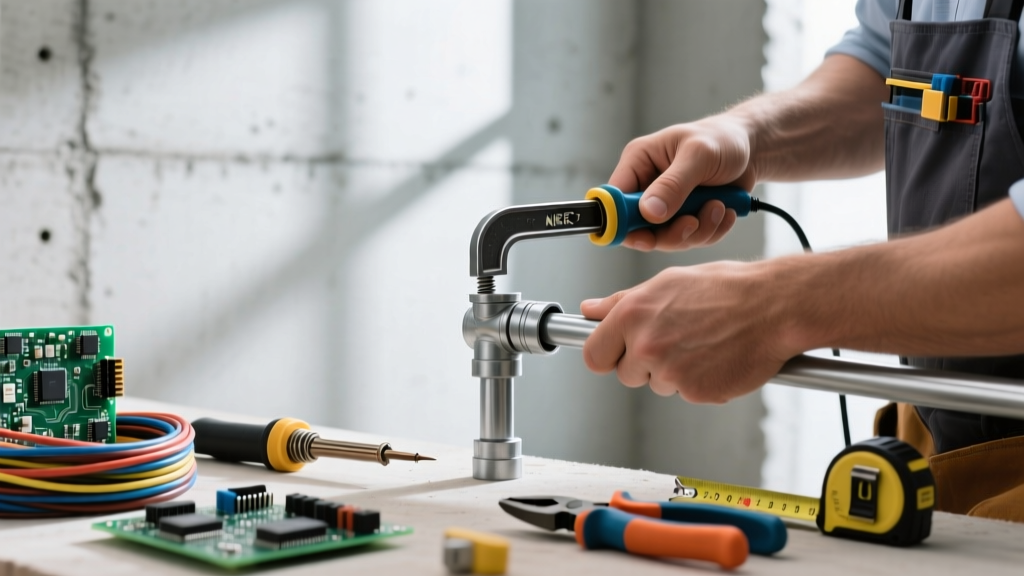
The tooling required for a saddle bend scales with the conduit material and diameter. For 1/2-inch to 1-inch EMT, a high-quality aluminum hand bender, such as the Klein Tools 516 series, provides the leverage and precision needed for clean saddles. However, commercial mechanical rooms frequently utilize Intermediate Metal Conduit (IMC) or Rigid Metal Conduit (RMC) in sizes ranging from 1-1/4 inches to 4 inches. Hand benders are entirely insufficient for these materials.
For IMC and RMC up to 4 inches, electricians must rely on mechanical benders like the Greenlee 881 series or heavy-duty Chicago benders. These mechanical ratcheting or hydraulic benders utilize segmented shoes that support the conduit wall during the bend, preventing the collapse or ovalization of the conduit profile. Ovalization is a critical failure mode in commercial rigid saddles, as it alters the internal diameter and can cause conductors to jam or suffer insulation abrasion during the pull.
Segment Bending for Massive Obstructions
When routing 5-inch or 6-inch RMC over massive structural obstructions, standard saddle bending is impossible due to the sheer force required and the risk of conduit deformation. In these scenarios, commercial electricians utilize 'segment bending.' This involves calculating a large radius and executing a series of micro-bends (typically 2 to 3 degrees each) spaced a few inches apart. The cumulative effect of these micro-bends creates a smooth, sweeping saddle that mimics a factory elbow, preserving the structural integrity of the heavy-wall conduit and minimizing wire pulling friction.
NEC Compliance and Support Requirements
Completing the bend is only half the battle; securing it to code is the final hurdle. The National Electrical Code (NEC) mandates strict support distances for all conduit types. For EMT (Article 358.30), conduit must be securely fastened within 3 feet of every outlet box, junction box, device box, or conduit body. When a saddle bend is executed near a box to clear a pipe, the physical geometry of the saddle often pushes the nearest straight section of conduit beyond the 3-foot limit. Commercial electricians must plan their Unistrut and threaded rod placements in advance, utilizing beam clamps and specialized strut brackets to secure the conduit immediately before and after the saddle's side bends. Failing to provide adequate support near a saddle bend results in sagging, which places undue mechanical stress on the junction box knockouts and can lead to ground continuity failures over time.
'A beautifully bent saddle means nothing if it sags under the weight of THHN copper. Always map your strut supports before you thread your first rod. The bend dictates the support, not the other way around.' — Commercial Electrical Foreman
Mastering the conduit bending saddle requires a synthesis of geometric mathematics, physical strength, and code compliance. By understanding the precise shrink multipliers, respecting the physics of wire pulling friction, and utilizing the correct mechanical tooling for the conduit type, commercial electricians can navigate the most congested mechanical spaces with precision and professionalism.