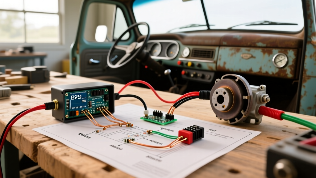

The Renovation Challenge: Aging Harnesses vs. Modern Towing
Renovating a classic truck—such as a 1990s Ford F-250, Chevy C/K Squarebody, or Dodge Ram Cummins—is a popular project for enthusiasts who want heavy-duty towing capability without the depreciation hit of a modern rig. However, when your renovation planning shifts from bodywork and suspension to the electrical system, you will inevitably hit a wall: the factory wiring harness. Original equipment manufacturer (OEM) harnesses from the 1980s and 1990s were designed for halogen headlights and simple resistive loads, not the sophisticated microprocessors found in modern proportional towing systems.
If you plan to tow a 7,000+ lb travel trailer or equipment hauler, integrating flawless electric brake controller wiring is non-negotiable. A poorly planned circuit will result in voltage drops, delayed braking response, or worse, a melted harness. This guide details the exact materials, circuit sizing, and routing protocols required to upgrade a vintage tow vehicle's electrical infrastructure for a modern controller like the Redarc Tow-Pro Elite V2 or the Tekonsha Prodigy P3.
Component Selection for Your Tow Vehicle Build
Before tearing into the dash, source the correct materials. Do not use off-the-shelf primary wire from a big-box hardware store; it lacks the chemical and heat resistance required for under-hood automotive environments.
- Brake Controller: Redarc Tow-Pro Elite V2 ($245) for dash-integrated knob control, or Tekonsha Prodigy P3 ($165) for traditional dash-mounted LCD units.
- Primary Wire: 10 AWG and 12 AWG Cross-Linked Polyethylene (XLPE) wire. Must meet the SAE J1128 Low-Tension Primary Cable Standard for high-temperature under-hood routing.
- Circuit Protection: Bussmann 184303 30-Amp Auto-Resetting Circuit Breaker ($18). Never use standard fuses for the main power feed, as transient voltage spikes during brake release can blow them repeatedly.
- Connectors: 7-Way Molded RV Blade Connector with 8-foot pigtail ($35) and heat-shrink ring terminals with adhesive lining.
- Tools: Ratcheting wire crimper (e.g., Titan 11938), digital multimeter, and a heat gun for adhesive shrink tubing.
Wire Gauge & Breaker Sizing Matrix
Sizing your electric brake controller wiring correctly depends on the Gross Vehicle Weight Rating (GVWR) of the trailer and the number of brake axles. Undersized wire causes voltage drop at the trailer brakes, resulting in weak stopping power.
| Trailer GVWR | Brake Axles | Main Power Wire (Battery to Controller) | Output Wire (Controller to 7-Way) | Breaker Size |
|---|---|---|---|---|
| Under 3,500 lbs | 1 | 12 AWG XLPE | 12 AWG XLPE | 20A Auto-Reset |
| 3,500 - 7,000 lbs | 1 or 2 | 10 AWG XLPE | 10 AWG XLPE | 30A Auto-Reset |
| 7,000 - 12,000 lbs | 2 or 3 | 10 AWG XLPE | 10 AWG XLPE (Dual Run) | 40A Auto-Reset |
Step-by-Step Wiring Integration
1. Sourcing the Stoplight Signal (The "Cold" Side)
The brake controller requires a 12V signal to know when you are pressing the brake pedal. In older trucks, this is sourced from the brake light switch at the pedal arm. You must identify the "cold" side of the switch—the wire that only has 12V when the pedal is depressed.
- Set your digital multimeter to DC Voltage.
- Back-probe the two wires at the brake pedal switch.
- With the pedal released, one wire will show 12V (hot side) and the other 0V.
- Press the pedal. The wire that transitions from 0V to 12V is your cold side stoplight signal.
Critical Renovation Trap: In many 1990s GM and Ford trucks, the Center High Mount Stop Lamp (CHMSL) or third brake light is powered by a Pulse Width Modulation (PWM) module to extend bulb life. If you tap into the CHMSL wire instead of the dedicated brake switch circuit, the PWM signal will feed back into the controller's logic board, causing it to throw an error code or fail entirely. Always verify a clean, solid 12V DC signal.
2. Routing the 12V Power and Ground
Voltage drop is the enemy of proportional braking. The controller must see full battery voltage to accurately modulate the output to the trailer.
- Power Feed: Run a 10 AWG red XLPE wire directly from the positive battery terminal to the 30A auto-resetting breaker. The breaker must be mounted within 18 inches of the battery to protect the entire length of the wire. From the breaker, route the wire through the firewall using an existing rubber grommet or a newly drilled hole sealed with a silicone firewall pass-through.
- Grounding: Do not ground the controller to the dash frame or a random sheet metal screw. Run a dedicated 10 AWG white ground wire from the controller directly to the negative battery terminal, or to a heavy-gauge chassis ground point. If using a chassis ground, sand the paint down to bare metal, use a star washer to bite into the steel, and coat the terminal in dielectric grease after tightening to prevent corrosion.
3. Terminating the 7-Way RV Connector
Under the rear bumper, you will need to install a 7-way RV blade connector. Adhere strictly to the RV Industry Association (RVIA) and SAE J2862 pinout standards to ensure compatibility with any rental or commercial trailer.
| Pin Position | Function | Wire Color | Wire Gauge |
|---|---|---|---|
| Pin 1 (Top Left) | Left Turn / Stop | Yellow | 12 AWG |
| Pin 2 (Top Right) | Electric Brakes | Blue | 10 AWG |
| Pin 3 (Bottom Left) | Ground | White | 10 AWG |
| Pin 4 (Bottom Right) | 12V Auxiliary Power | Black | 10 AWG |
| Pin 5 (Center) | Right Turn / Stop | Green | 12 AWG |
| Pin 6 (Top Center) | Tail / Marker Lights | Brown | 12 AWG |
| Pin 7 (Bottom Center) | Reverse Lights / Aux | Purple | 12 AWG |
Run the blue 10 AWG output wire from the controller under the truck, securing it every 18 inches with UV-resistant zip ties to the frame rail. Keep it away from the exhaust system and moving suspension components. For detailed routing diagrams and vehicle-specific plug locations, the etrailer.com Wiring FAQ remains an indispensable resource for custom tow builds.
Common Failure Modes in Renovated Trucks
1. The "Phantom Braking" Ground Loop: If the trailer brakes apply slightly when you turn on the truck's headlights, you have a bad ground at the 7-way connector. The brake circuit is back-feeding through the taillight circuit to find a path to ground. Clean the 7-way plug contacts and verify the white ground wire is bonded to bare chassis metal.
2. Melted Connectors: Using standard 12 AWG wire for a 3-axle trailer pulling 40+ amps will cause the wire insulation to melt and short against the frame. Always use 10 AWG for the blue brake output wire on trailers over 5,000 lbs.
3. Corroded Firewall Pass-Throughs: Failing to seal the hole where the power wire enters the cab allows water to wick into the dash, corroding the controller's internal PCB within a single winter season.
Testing and Calibration Before the Maiden Voyage
Once the physical installation is complete, do not immediately hook up the trailer. Turn the ignition to the "ON" position (engine off). The controller should power up and display a initialization sequence. Use your multimeter to check the voltage at the blue wire pin on the 7-way connector while a helper presses the brake pedal. You should see the voltage climb smoothly from 0V to roughly 12V (or your set gain percentage). If the voltage jumps erratically or fails to reach at least 11.5V at the plug, you have excessive resistance in the circuit and must re-crimp your connections.
After verifying the bare wiring, connect the trailer. Set the controller gain to 6.0, drive to 25 MPH in an empty lot, and apply the manual override lever on the controller. If the truck and trailer stop in a straight line without the trailer tires locking up, your renovation planning has paid off. Adjust the gain up or down by 0.5 increments until the braking feels seamless.
Frequently Asked Questions
Can I use the factory tow package wiring in my 1990s truck?
Most 1980s and 1990s trucks did not come with a true "tow package" wiring harness that included the heavy-gauge 10 AWG blue brake output wire. They typically only included a 4-way flat connector for lights. You will almost certainly need to run a new dedicated 10 AWG blue wire from the cab to the rear bumper for the electric brakes.
Why does my brake controller display an "SH" or "OL" error code?
"SH" indicates a Short to Ground, and "OL" indicates an Overload. In a renovation context, this usually means the blue output wire has rubbed through its insulation against the steel frame rail under the truck, or the 7-way connector has internal corrosion bridging the brake pin to the ground pin. Inspect the entire length of the blue wire and replace the 7-way plug if the pins are green with oxidation.
Do I need a relay for the 12V auxiliary pin on the 7-way?
Yes. If you are wiring Pin 4 (12V Auxiliary) to charge a trailer breakaway battery or power interior trailer lights, do not run it directly from the battery. Use a 40A continuous-duty solenoid relay triggered by the ignition switch. This prevents the trailer from draining your truck's starting battery when the vehicle is parked and the ignition is off.