
The High Cost of Neglecting Arduino Wiring Safety
In the modern DIY electronics landscape of 2026, microcontrollers are more powerful and accessible than ever. However, the fundamental physics of electricity remain unforgiving. A single misplaced jumper wire or an ignored current limit can instantly destroy a $25 Arduino board, turning a weekend project into an expensive troubleshooting nightmare. Whether you are prototyping with a classic 5V Uno R3 or deploying a 3.3V Nano ESP32 in a commercial enclosure, adhering to strict Arduino wiring safety protocols is non-negotiable.
This guide moves beyond basic tutorials to explore the deep technical realities of microcontroller protection, focusing on failure modes, current thresholds, and physical wiring integrity.
The Golden Rule of Microcontroller Wiring: Never wire or modify a circuit while the board is powered. Always disconnect USB and external power supplies before moving jumper wires. Hot-swapping connections is the leading cause of accidental short circuits and GPIO latch-up events.
Voltage and Current Limits: Knowing Your Board's Thresholds
The most common cause of catastrophic board failure is exceeding the maximum current or voltage ratings of the General Purpose Input/Output (GPIO) pins. Many beginners assume a digital pin can power a small motor or a high-brightness LED directly. This is a critical error.
According to the official Arduino hardware documentation, standard ATmega328P-based boards have strict limits that, if violated, will melt internal silicon traces or destroy the microcontroller's port registers.
Board-Specific Pin Limits and Tolerances
| Board Model (2026 Standard) | Logic Level | Max I/O Pin Current | Absolute Max I/O Current | Max 5V/3.3V Rail Current |
|---|---|---|---|---|
| Arduino Uno R3 | 5V | 20 mA | 40 mA | 500 mA (USB) / 800 mA (Barrel) |
| Arduino Nano 33 IoT | 3.3V | 7 mA | 15 mA | 150 mA |
| Arduino Uno R4 Minima | 5V | 8 mA | 25 mA | 1.5 A (via USB-C PD) |
| Arduino Nano ESP32 | 3.3V | 12 mA | 40 mA (specific pins) | 500 mA |
Failure Mode Analysis: Connecting a standard 5V relay coil directly to a digital pin draws between 70 mA and 120 mA. This instantly exceeds the 40 mA absolute maximum of an Uno R3, causing the internal output transistor to overheat and short out. Always use a logic-level MOSFET (like the IRLZ44N) or a dedicated relay driver module to switch inductive loads.
Preventing Back-EMF and Inductive Kickback
When you wire inductive components—such as DC motors, solenoids, or relay coils—you are storing energy in a magnetic field. When the Arduino pin drops to LOW and cuts the power, that collapsing magnetic field generates a massive reverse voltage spike known as Back-Electromotive Force (Back-EMF). This spike can easily exceed 50V, instantly piercing the gate oxide of your microcontroller's GPIO pins.
The Flyback Diode Solution
To protect your Arduino wiring from inductive kickback, you must install a flyback diode in reverse bias across the inductive load. As detailed in SparkFun's comprehensive diode guide, the diode provides a safe recirculation path for the collapsing current.
- Component Selection: Use a standard 1N4007 rectifier diode for most 12V and 24V relays and motors. For high-frequency switching (like PWM motor control), use a fast-recovery Schottky diode like the 1N5819 to prevent diode overheating.
- Placement: The diode must be placed as physically close to the inductive load's terminals as possible, not near the Arduino pins. The cathode (silver stripe) faces the positive voltage supply.
Power Supply Isolation and Grounding Strategies
Mixing high-current loads (like stepper motors or heating elements) with sensitive microcontroller logic on the same power bus is a recipe for ground bounce and erratic resets. When a high-current device activates, it pulls voltage down on the shared ground wire, which the Arduino interprets as a floating or noisy signal.
Implementing Optocouplers for Galvanic Isolation
For industrial or high-noise environments, physical separation of logic and power is required. Use an optocoupler, such as the ubiquitous PC817, to bridge the gap. The Arduino wiring connects only to the internal LED of the optocoupler, while the high-voltage side is wired to the internal phototransistor. This ensures that even if a 120V AC fault occurs on the load side, the high voltage cannot cross the optical gap to destroy your computer's USB port via the Arduino.
Common Ground Requirements
If you are using separate power supplies (e.g., a 5V USB supply for the Arduino and a 12V wall adapter for a motor driver like the A4988), you must tie the grounds together. Without a common ground reference, the logic signals sent from the Arduino to the motor driver will float unpredictably, causing the driver to misinterpret steps or lock up entirely.
Physical Wiring Best Practices and Tool Selection
Safety is not just about electrical theory; it is about the physical integrity of your connections. Poor physical wiring leads to high-resistance joints, localized heating, and intermittent faults.
Wire Gauge and Breadboard Limitations
Breadboards are designed for low-current signal prototyping, not power distribution. The Arduino breadboard guidelines note that standard solderless breadboard contacts degrade over time, increasing contact resistance. Pushing 2A through a breadboard power rail to feed a servo array will melt the internal metal clips.
- Prototyping Phase: Use 22 AWG solid-core copper wire for breadboards. Stranded wire frays when inserted into breadboard contacts, leaving behind tiny copper splinters that cause hidden short circuits between adjacent rows.
- Permanent Deployment: Transition to 18 AWG stranded wire for power rails and motor connections. Always crimp ferrule ends onto stranded wire before inserting them into screw terminals (like those on motor shields). This prevents the screw from crushing the copper strands, which reduces the wire's cross-sectional area and creates a fire hazard.
Troubleshooting Common Wiring Faults: A Multimeter Checklist
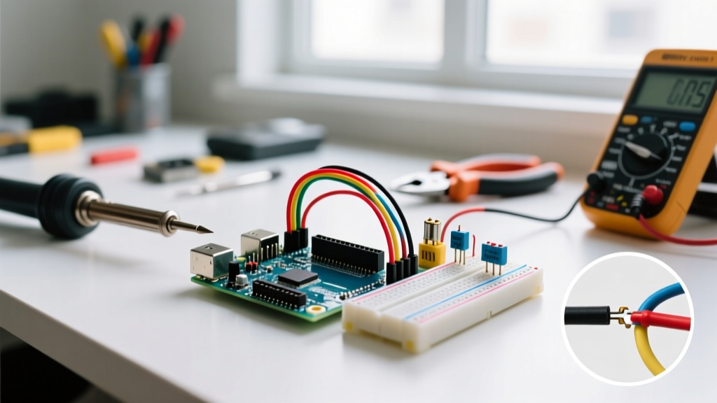
Before applying power to a newly wired Arduino project for the first time, perform this mandatory safety checklist using a digital multimeter (DMM):
- Continuity Check (Power Off): Set your DMM to continuity mode. Place one probe on the 5V/3.3V rail and the other on the GND rail. If the meter beeps, you have a dead short. Do not apply power until the short is found.
- Voltage Verification (Power On, Board Disconnected): Power your external supply and measure the voltage at the end of your wiring harness. Ensure a 5V supply is not accidentally outputting 12V due to a misconfigured variable bench supply.
- Voltage Drop Test (Under Load): With the system running, measure the voltage directly at the Arduino's VIN pin and compare it to the voltage at the power supply terminals. A drop of more than 0.3V indicates your power wires are too thin (too high AWG) for the current draw.
Conclusion
Mastering Arduino wiring safety requires a shift in mindset from simply "making it work" to engineering for reliability and failure prevention. By respecting current limits, neutralizing inductive kickback with flyback diodes, isolating high-power loads, and using the correct wire gauges, you ensure your microcontrollers survive the prototyping phase and thrive in long-term deployment.