
The Evolution of Arduino LCD Screen Wiring
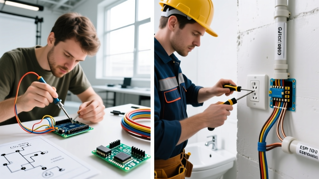
Interfacing a liquid crystal display with a microcontroller is a foundational rite of passage in electronics. However, the methodology behind Arduino LCD screen wiring diverges drastically depending on the end goal. A hobbyist building a one-off weather station on a kitchen table faces entirely different constraints than an electrical engineer designing a commercial HVAC control panel. While the underlying communication protocols—typically 4-bit parallel or I2C—remain identical, the physical wiring topology, material selection, and quality assurance standards separate fragile prototypes from field-deployable products.
In this analysis, we deconstruct the DIY approach versus professional wire harness integration for character and TFT LCD modules, examining signal integrity, mechanical reliability, and real-world BOM (Bill of Materials) costs as of 2026.
The Prototyping Phase: DIY Breadboard Wiring
The standard DIY approach to Arduino LCD screen wiring usually involves a 16x2 or 20x4 character LCD based on the ubiquitous Hitachi HD44780 controller. Hobbyists typically wire these displays using one of two methods:
1. Direct 4-Bit Parallel Wiring
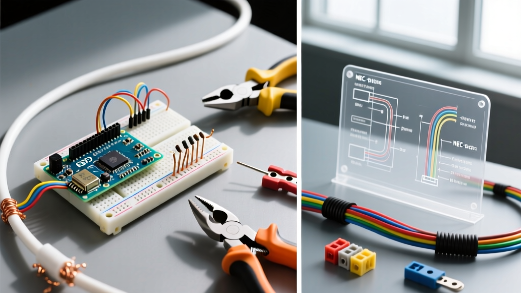
This method requires six digital GPIO pins (RS, Enable, D4, D5, D6, D7) plus power, ground, and a 10kΩ potentiometer for the V0 contrast pin. DIY builders rely on 28 AWG solid-core Dupont jumper wires pushed into a solderless breadboard. While excellent for rapid iteration, solid-core wire fatigues quickly when bent, and breadboard contacts suffer from oxidation and low normal force, leading to intermittent connections.
2. The I2C Backpack Solution
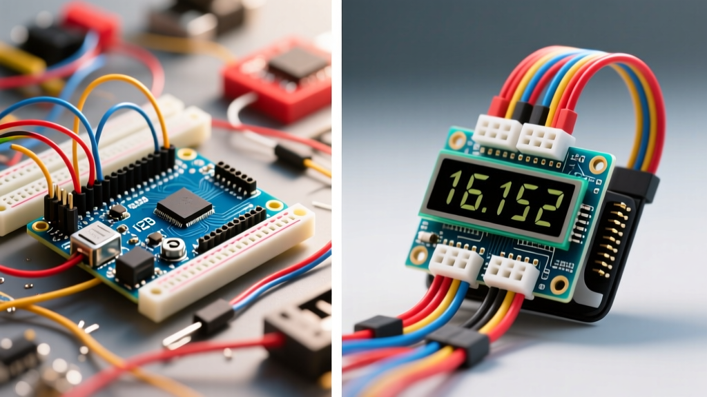
To save GPIO pins, the DIY community heavily favors the PCF8574 I2C backpack. This reduces the wiring to just four lines: VCC, GND, SDA, and SCL. As of 2026, the supply chain for the PCF8574 expander chip has fully stabilized, dropping bulk unit costs to roughly $0.45. For comprehensive setup instructions on these modules, the Adafruit I2C LCD Backpack Guide remains an excellent foundational resource for hobbyists.
DIY Failure Mode: The most common point of failure in breadboard I2C wiring is voltage drop across long, thin jumper wires. If the 5V line sags below 4.5V under the backlight's 80mA load, the HD44780 controller will brown out, resulting in a frozen display or corrupted memory registers.
Professional Integration: Wire Harnesses and IPC Standards
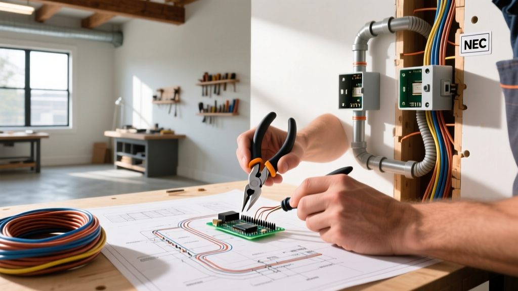
When transitioning from a prototype to a manufactured product, professional electrical engineers abandon solderless breadboards and Dupont wires entirely. Professional Arduino LCD screen wiring utilizes custom wire harnesses terminated with friction-lock or positive-latch connectors.
Connector Selection: JST-XH vs. Molex PicoBlade
For internal chassis wiring to an LCD module, professionals select connectors based on pitch, current rating, and vibration resistance:
- JST-XH (2.54mm pitch): The industry workhorse for 16-pin LCD ribbons. It features a friction lock that prevents the connector from vibrating loose in industrial environments. Rated for 3A per circuit, it easily handles the LCD backlight current.
- Molex PicoBlade (1.25mm pitch): Used in ultra-compact consumer electronics where PCB real estate is at a premium. Requires precision crimping tools (like the Molex 63819-0000) to ensure a gas-tight connection.
Adhering to IPC/WHMA-A-620 Standards
Professional wire harness assemblies are governed by the IPC/WHMA-A-620 standard. This dictates strict criteria for wire preparation, crimp quality, and strain relief. In a professional setting, a wire harness connecting an Arduino-compatible PLC to an LCD panel will feature:
- Stranded Copper Wire (24 or 26 AWG): Stranded wire withstands continuous flexing and thermal expansion cycles without breaking, unlike solid-core DIY wire.
- Heat-Shrink Tubing with Adhesive Lining: Applied at the connector backshell to provide strain relief and prevent moisture ingress.
- Pull-Force Testing: Every crimp batch is destructively tested to ensure the wire breaks before the crimp barrel yields.
Signal Integrity: I2C Bus Capacitance and EMI
The most critical engineering challenge in professional Arduino LCD screen wiring over long distances (greater than 30cm) is maintaining I2C signal integrity. The I2C bus is highly susceptible to parasitic capacitance and electromagnetic interference (EMI).
According to the NXP UM10204 I2C Specification, the standard I2C bus limits total bus capacitance to 400pF. Every centimeter of wire, every connector pin, and the LCD controller's internal circuitry adds parasitic capacitance. In a DIY setup with 10cm jumper wires, this limit is never approached. In an industrial enclosure with a 1.5-meter cable run to a door-mounted LCD, the capacitance easily exceeds 400pF, rounding off the square-wave edges of the SDA/SCL signals and causing ACK/NACK communication failures.
Professional Mitigation Strategies
| Mitigation Technique | Implementation Details | Cost Impact (Per Unit) |
|---|---|---|
| Lower Pull-Up Resistors | Swap standard 4.7kΩ pull-ups for 2.2kΩ or 1.5kΩ to charge bus capacitance faster. | +$0.02 |
| Twisted Pair Wiring | Twist SDA with GND, and SCL with GND to reduce crosstalk and inductive loop area. | +$0.45 |
| I2C Bus Extenders | Use a PCA9615 differential I2C transceiver for runs exceeding 2 meters. | +$1.85 |
| Foiled Shielding (F/UTP) | Wrap the harness in aluminum foil shield with a stranded drain wire tied to chassis ground. | +$1.20 |
Cost and Scalability Matrix: DIY vs. Professional
Understanding the economic reality of Arduino LCD screen wiring requires looking beyond the cost of a single prototype. Below is a comparative BOM analysis for the physical wiring components (excluding the LCD and microcontroller themselves).
| Category | DIY / Hobbyist Approach | Professional / Production Approach |
|---|---|---|
| Wire Type | 28 AWG Solid Core Dupont ($0.05/ea) | 26 AWG Stranded UL1007 ($0.12/meter) |
| Connectors | Generic friction headers ($0.10) | JST-XH with locking ramp ($0.35) |
| Assembly Labor | Self (Solderless / Hand Solder) | Automated cut/strip/crimp machine |
| Testing | Visual / Functional Power-On | Continuity, Hipot, and Pull-Test |
| Est. Harness Cost (1 Unit) | $1.50 | $8.50 |
| Est. Harness Cost (10,000 Units) | N/A (Not scalable) | $2.15 (Economies of scale) |
Real-World Failure Mode Analysis
When field-deployed devices fail, the wiring harness is often the culprit. Here are three specific failure modes observed in improperly executed LCD wiring projects:
- Thermal Cycling Fatigue: In outdoor enclosures (e.g., solar charge controllers), temperatures can swing from -10°C to 60°C. Solid-core DIY wires expand and contract at different rates than the PCB pads, eventually snapping the solder joint at the LCD header. Stranded wire with proper strain relief absorbs this mechanical stress.
- Galvanic Corrosion: Using cheap, un-gold-plated Dupont pins in high-humidity environments (like greenhouse automation) leads to tin oxidation. This increases contact resistance, causing the I2C logic high voltage to drop below the Arduino's 0.7*VCC threshold, resulting in silent communication drops.
- Backlight Inrush Damage: A 20x4 LCD with an LED backlight can draw up to 120mA. If a DIY builder routes this through a standard breadboard trace or a thin 28 AWG jumper, the localized resistance generates heat, melting the plastic connector housing and creating a short-circuit hazard.
Final Verdict: When to Upgrade Your Wiring
If your project lives permanently on a desk in a climate-controlled room, DIY Arduino LCD screen wiring with I2C backpacks and Dupont cables is perfectly adequate. However, the moment your device is subjected to vibration, thermal extremes, or requires UL/CE certification for commercial sale, you must adopt professional wire harness methodologies. Investing in JST-XH connectors, stranded UL-rated wire, and adhering to IPC crimping standards ensures your display interface remains as reliable as the code driving it.