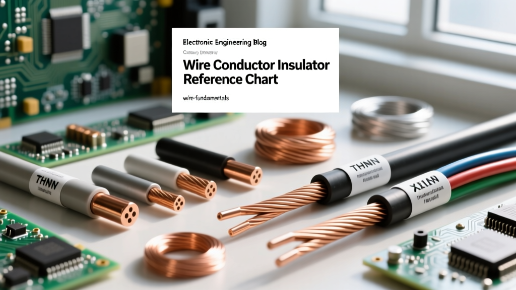

The Core Partnership: Conductor and Insulator Fundamentals
Every functional electrical circuit relies on a critical, symbiotic partnership: the conductor and its surrounding insulator. While the conductor provides the low-resistance pathway for electron flow, the insulator confines that energy, preventing short circuits, ground faults, and lethal shock hazards. Understanding the material science behind both elements is not just an academic exercise; it is the foundation of safe electrical design, NEC compliance, and long-term system reliability.
In this comprehensive reference guide, we will dissect the metallurgical properties of common conductors, evaluate the dielectric and thermal limits of modern insulation polymers, and provide actionable data charts for sizing and troubleshooting. Whether you are sizing feeders for a 400-amp residential service or selecting high-temperature wire for an industrial control panel, the interaction between the conductor and the dielectric jacket dictates your safety margins.
Conductor Materials: Resistivity and Ampacity Metrics
The choice of conductor material directly impacts voltage drop, heat dissipation, and physical weight. While copper remains the undisputed king of residential and commercial wiring due to its high conductivity and tensile strength, aluminum has seen a massive resurgence in utility feeders and heavy commercial applications due to its cost-to-weight ratio. However, selecting the right metal requires understanding specific resistivity and the National Electrical Code (NEC) mandates.
According to the Copper Development Association, annealed copper sets the standard for electrical conductivity at 100% IACS (International Annealed Copper Standard). Aluminum, by contrast, operates at roughly 61% IACS. This means an aluminum conductor must be physically larger (typically two AWG sizes up) to carry the same ampacity as a copper equivalent. Furthermore, NEC Article 310.106 strictly mandates that solid or stranded aluminum conductors sized 12 AWG through 1000 kcmil must be made of AA-8000 series electrical grade aluminum alloy to prevent the cold-creep and thermal expansion issues that plagued older AA-1350 alloys in the 1970s.
Reference Chart: Conductor Metallurgy & Electrical Properties
| Material | Resistivity (Ω·CM/ft @ 20°C) | Relative Conductivity (IACS) | Primary Application & Notes |
|---|---|---|---|
| Copper (Cu) | 10.4 | 100% | Branch circuits, high tensile strength, standard for residential/commercial. |
| Aluminum (AA-8000) | 17.0 | 61% | Service entrance feeders, lightweight, requires anti-oxidant paste & specific torque. |
| Silver (Ag) | 9.8 | 105% | RF applications, high-frequency skin effect mitigation, aerospace. |
| Gold (Au) | 14.5 | 70% | Corrosion-resistant plating for low-voltage data/audio contacts and microcontrollers. |
Insulation Polymers: Thermal Limits and Dielectric Strength
The insulator is the unsung hero of wire sizing. A conductor's ability to carry current (ampacity) is entirely limited by the thermal threshold of its insulation. If the heat generated by I²R losses exceeds the polymer's glass transition or melting point, the dielectric breaks down, leading to catastrophic arcing. Modern wire manufacturing relies on a few key polymer families, each with distinct advantages when pairing the conductor and the dielectric shield.
Reference Chart: Common Insulation Types & Thermal Ratings
| Insulation Type | Dielectric Material | Max Temp (Dry / Wet) | Best Application & Characteristics |
|---|---|---|---|
| THHN / THWN-2 | PVC with Nylon Jacket | 90°C / 75°C | General indoor conduit. Nylon provides mechanical abrasion resistance but degrades in continuous moisture. |
| XHHW-2 | Cross-Linked Polyethylene (XLPE) | 90°C / 90°C | Superior water resistance, no nylon degradation, excellent dielectric strength for wet locations. |
| MI (Mineral Insulated) | Compressed Magnesium Oxide (MgO) | 250°C+ | Critical life-safety circuits, fireproof, highly rigid, requires specialized termination kits. |
| PTFE (Teflon) | Fluoropolymer | 200°C+ | Aerospace, high-frequency data, low dielectric loss, extreme chemical resistance. |
NEC Derating: When the Conductor and Thermal Environments Collide
A common mistake among junior electricians and DIYers is reading the 90°C column of NEC Table 310.16 and assuming the wire can safely carry that full load in a real-world installation. In reality, the 90°C rating is primarily used for derating calculations. When you bundle more than three current-carrying conductors in a single raceway, or when ambient temperatures exceed 86°F (30°C), the heat generated by the conductor and the surrounding wires accumulates.
Per NFPA 70 (NEC) Article 310.15, the final derated ampacity must not exceed the temperature rating of the weakest termination point in the circuit, which is typically rated at 75°C or 60°C.
For example, if you pull four current-carrying THHN conductors through an attic where the ambient temperature reaches 110°F (43°C), you must apply both the ambient temperature correction factor and the bundling adjustment factor. The resulting ampacity often forces you to upsize the wire by two or three AWG gauges to maintain a safe operating temperature for the insulation.
Calculating Voltage Drop: The Conductor and Circular Mil Formula
Beyond thermal limits, the physical cross-sectional area of the conductor dictates voltage drop over distance. To accurately calculate this, electrical engineers use the Circular Mil (CM) formula. The relationship between the conductor and voltage drop is expressed as:
VD = (2 x K x I x L) / CM
- VD: Voltage Drop (target < 3% for branch circuits, < 5% total system)
- K: Specific Resistance (12.9 for Copper, 21.2 for Aluminum at 75°C)
- I: Current in Amperes
- L: One-way length of the circuit in feet
- CM: Circular Mils of the conductor (e.g., 10 AWG = 10,380 CM)
For example, if you are running a 50-amp subpanel feeder 150 feet using aluminum, the higher 'K' value of 21.2 forces you to upsize the wire significantly compared to copper to prevent a voltage drop that could damage sensitive microcontroller-based appliances or cause HVAC compressors to stall and overheat.
Advanced Failure Modes: Tracking, Water Treeing, and Galvanic Action
Understanding how the conductor and insulation fail in the field is crucial for troubleshooting and forensic electrical analysis. Here are three specific failure modes that dictate material selection in harsh environments:
1. Galvanic Corrosion at Terminations
When a copper conductor and an aluminum termination lug meet in the presence of moisture, a galvanic cell is formed. Aluminum acts as the anode and corrodes rapidly, increasing contact resistance. This high resistance generates localized heat, eventually melting the lug and starting a fire. Always use bi-metallic (tin-plated) lugs and apply Noalox anti-oxidant paste when bridging these two metals.
2. Water Treeing in XLPE
Cross-linked polyethylene (XLPE) is an excellent insulator, but when subjected to continuous high-voltage stress in wet environments, microscopic 'water trees' can form within the dielectric matrix. These dendritic micro-channels eventually bridge the gap between the conductor and the ground shield, causing a massive dielectric breakdown. For direct-burial wet applications, tree-retardant XLPE (TR-XLPE) or a continuous metallic moisture barrier is required.
3. Nylon Jacket Degradation (THHN)
THHN wire features a PVC base insulation and a thin Nylon outer jacket. While the nylon provides excellent mechanical abrasion resistance during wire pulling, it is highly susceptible to degradation when exposed to continuous moisture or certain hydrocarbons. In wet locations, the nylon can hydrolyze and flake off, leaving the PVC vulnerable to plasticizer loss and embrittlement. This is why THWN-2 or XHHW-2 (which lacks nylon but uses a thicker, water-resistant XLPE jacket) is the superior choice for wet conduit runs and underground PVC.
Summary: Matching the Conductor and the Application
Selecting the correct wire is never just about matching an AWG size to a breaker. It requires a holistic evaluation of the conductor and its insulating materials, factoring in ambient heat, bundling derations, voltage drop over distance, and environmental hazards. By leveraging the reference charts above and adhering to NEC thermal limits, you ensure your electrical infrastructure remains safe, efficient, and resilient for decades. Always consult manufacturer data sheets from trusted suppliers like Southwire Technical Resources when operating at the extreme edges of thermal and dielectric tolerances.


