
The Quantum Boundary: Defining Electric Conductors and Insulators
At the heart of every electrical system lies a fundamental binary: the path of least resistance and the barrier that contains it. Understanding the physics of electric conductors and insulators is not just academic; it is the bedrock of safe wire sizing, voltage drop mitigation, and high-voltage isolation. In solid-state physics, the distinction between a conductor and an insulator is defined by the band gap—the energy difference between the valence band (where electrons are bound to atoms) and the conduction band (where electrons flow freely).
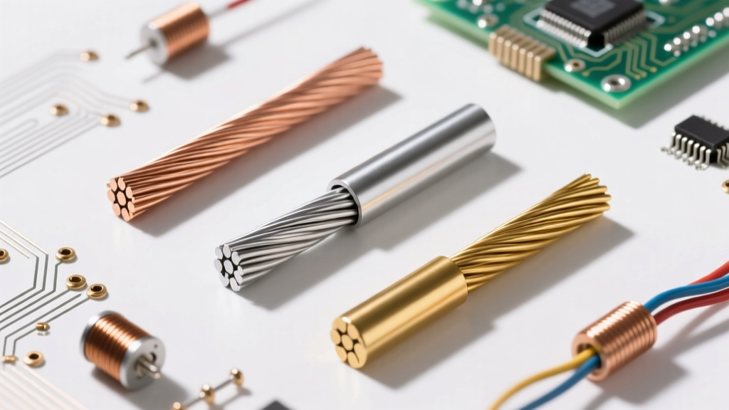
Conductors, like copper and aluminum, have overlapping bands, allowing free electron movement with minimal energy input. Insulators, such as PVC, XLPE, and Teflon, possess a wide band gap (typically greater than 3 eV), requiring massive electrical stress to force electrons into the conduction band. As a DIY enthusiast or professional electrician, mastering the calculations that govern these materials ensures your circuits operate efficiently without catastrophic dielectric failure.
Core Calculation 1: Conductor Resistivity and Voltage Drop
To size a wire correctly, you must first calculate its baseline resistance. The resistance of any conductor is dictated by its material resistivity, length, and cross-sectional area. According to Georgia State University HyperPhysics, the fundamental formula for DC resistance is:
R = ρ × (L / A)
- R = Resistance in Ohms (Ω)
- ρ (rho) = Resistivity of the material (for annealed copper at 20°C, ρ ≈ 1.724 × 10⁻⁸ Ω·m)
- L = Length of the conductor in meters
- A = Cross-sectional area in square meters
Practical Example: Sizing a 240V EV Charger Circuit
Suppose you are wiring a 40-amp Level 2 EV charger located 50 meters (164 feet) from your main panel using copper wire. You select 8 AWG THHN, which has a cross-sectional area of 8.37 mm² (8.37 × 10⁻⁶ m²). Because current must travel to the load and back, the total circuit length (L) is 100 meters.
R = (1.724 × 10⁻⁸ Ω·m × 100 m) / (8.37 × 10⁻⁶ m²)
R = 0.206 Ω
Using Ohm’s Law (V = I × R), the voltage drop at 40 amps is:
V_drop = 40A × 0.206Ω = 8.24V
This represents a 3.4% drop on a 240V circuit, which is safely within the National Electrical Code (NEC) recommendation of keeping voltage drop under 5% for branch circuits.
Temperature Derating: The Real-World Variable
Wire resistance is not static; it increases as the conductor heats up. If your 8 AWG wire is routed through a hot attic or bundled with other current-carrying conductors, its temperature may reach 75°C. We calculate the adjusted resistance using the temperature coefficient formula:
R_T = R_20 × [1 + α(T - 20)]
For copper, the temperature coefficient (α) is 0.00393 per °C.
R_75 = 0.206 × [1 + 0.00393(75 - 20)]
R_75 = 0.206 × [1 + 0.216] = 0.250 Ω
At operating temperature, your voltage drop increases to 10V (4.1%). This calculation proves why thermal management and derating tables in the NEC are critical for preventing thermal runaway.
Core Calculation 2: Insulator Dielectric Strength and Breakdown
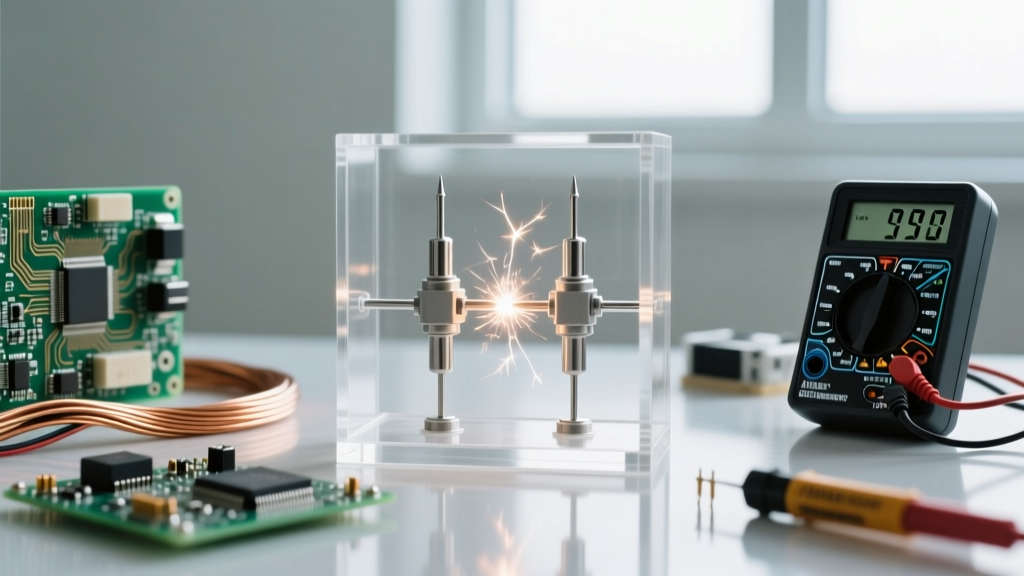
While conductors are measured by their willingness to pass current, electric insulators are measured by their ability to resist it—until they fail. Dielectric strength is the maximum electric field an insulating material can withstand before it breaks down and becomes conductive. It is typically measured in kilovolts per millimeter (kV/mm).
The breakdown voltage calculation is straightforward:
V_breakdown = E_strength × d
- V_breakdown = Voltage at which insulation fails
- E_strength = Dielectric strength of the material
- d = Thickness of the insulation in mm
Comparing PVC vs. XLPE in High-Stress Environments
Let us compare standard Polyvinyl Chloride (PVC) and Cross-Linked Polyethylene (XLPE), two common insulators used in residential and commercial wiring.
- PVC Dielectric Strength: ~24 kV/mm
- XLPE Dielectric Strength: ~20 to 25 kV/mm (but vastly superior thermal and chemical resistance)
If you are using a specialized high-voltage probe wire with a thin 0.5mm insulation jacket made of PTFE (Teflon, dielectric strength ~60 kV/mm), the theoretical breakdown voltage is:
V_breakdown = 60 kV/mm × 0.5 mm = 30 kV (30,000 Volts)
However, real-world factors like microscopic voids in the extrusion process, moisture ingress, and partial discharge can lower this threshold by up to 40%. This is why the National Electrical Manufacturers Association (NEMA) mandates rigorous hi-pot (high potential) testing during manufacturing to ensure the insulation can handle transient voltage spikes without arcing.
Advanced Diagnostics: Calculating Leakage and Polarization Index
No insulator is perfect. When voltage is applied, a tiny amount of current—known as leakage current—flows through and over the surface of the insulation. In aging motor windings or long underground feeder cables, calculating this leakage is vital for predictive maintenance.
Using a Megohmmeter (Megger), technicians apply a high DC voltage (e.g., 1000V) and measure the insulation resistance (IR). According to the Fluke Insulation Resistance Testing Guide, you can calculate the leakage current:
I_leakage = V_applied / R_insulation
If a 480V industrial motor shows an insulation resistance of 50 MΩ (Megohms):
I_leakage = 480V / 50,000,000 Ω = 9.6 µA (microamps)
While 9.6 µA seems negligible, in sensitive medical equipment or GFCI-protected circuits (which trip at 4-6 mA), cumulative leakage across multiple degraded insulators can cause nuisance tripping.
The Polarization Index (PI) Calculation
To determine if insulation is contaminated with moisture or oil, professionals calculate the Polarization Index. This requires taking two resistance readings over time:
PI = R_10min / R_1min
- PI < 1.0: Dangerous. Insulation is likely wet or heavily contaminated. Immediate drying or replacement is required.
- PI 1.0 - 2.0: Questionable. Monitor closely.
- PI > 2.0: Excellent. Insulation is dry and healthy.
For example, if your 1-minute reading is 100 MΩ and your 10-minute reading is 450 MΩ, your PI is 4.5. This indicates strong dielectric absorption, meaning the insulator's molecular dipoles are aligning properly under the electric field, confirming healthy insulation.
Material Selection Matrix for Wiring Projects
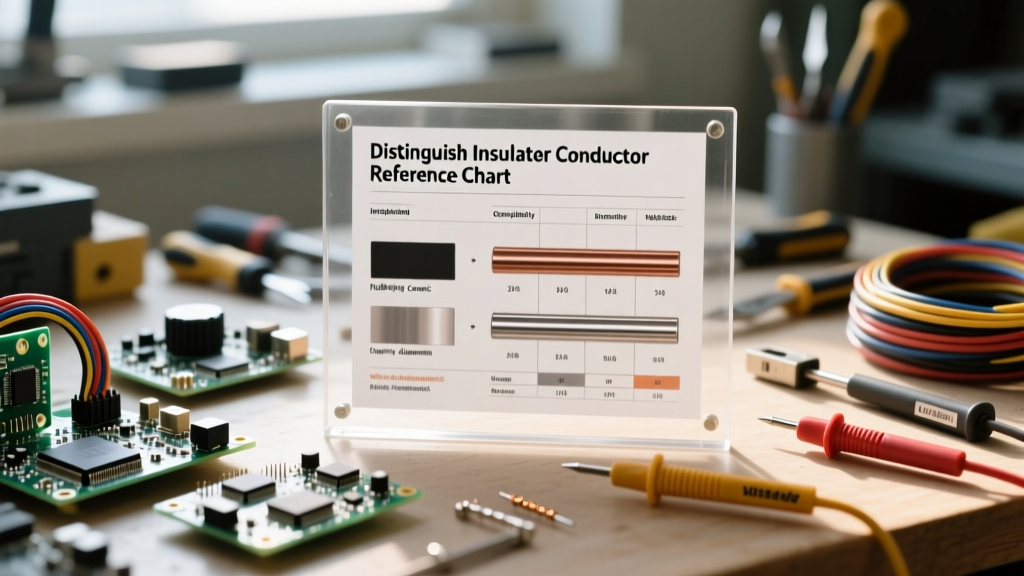
Choosing the right pairing of electric conductors and insulators requires balancing electrical efficiency, thermal limits, and environmental factors. Use the table below as a quick reference for your next DIY or professional installation.
| Material Type | Role | Key Metric (Resistivity / Dielectric) | Max Operating Temp | Best Application |
|---|---|---|---|---|
| Copper (Cu) | Conductor | 1.68 × 10⁻⁸ Ω·m | N/A (Melts 1085°C) | Standard branch circuits, high-efficiency motors |
| Aluminum (Al) | Conductor | 2.82 × 10⁻⁸ Ω·m | N/A (Melts 660°C) | Heavy feeder cables, service entrance conductors |
| PVC | Insulator | ~24 kV/mm | 75°C to 105°C | Standard THHN/THWN building wire |
| XLPE | Insulator | ~20-25 kV/mm | 90°C to 250°C (short circuit) | Underground direct burial, high-temp industrial |
| PTFE (Teflon) | Insulator | ~60 kV/mm | 260°C | Aerospace, thermocouple wire, high-frequency RF |
Safety Warning: Never assume an insulator's dielectric strength is infinite. Transient voltage spikes (such as lightning strikes or inductive kickback from large motors) can momentarily exceed the peak dielectric threshold of standard PVC, causing micro-punctures. These punctures create carbon tracks, permanently turning a localized section of the insulator into a conductor and leading to eventual short circuits or fires. Always use surge protective devices (SPDs) to protect vulnerable insulation systems.