
Whether you are wiring an off-grid solar array or troubleshooting a mains-powered workshop tool, understanding how electrons move through a conductor is the bedrock of electrical safety and efficiency. While textbooks often rely on abstract sine waves and water-pipe analogies, finding a practical, real-world example of direct current and alternating current is essential for DIYers and electricians who need to make informed decisions about wire sizing, component selection, and circuit protection.
The Core Physics: Electrons in Motion
At the atomic level, current is the flow of electrons. The distinction between Direct Current (DC) and Alternating Current (AC) lies entirely in the direction and consistency of that flow.
- Direct Current (DC): Electrons flow continuously in a single direction, from the negative terminal to the positive terminal. The voltage remains constant over time (ignoring minor ripple or battery sag).
- Alternating Current (AC): Electrons rapidly reverse direction, oscillating back and forth within the conductor. In North America, this occurs 60 times per second (60 Hz), meaning the current changes direction 120 times per second.
According to the U.S. Department of Energy, AC became the global standard for power grids because it is vastly easier to step voltage up and down using transformers, minimizing transmission losses over long distances. DC, however, remains the undisputed king of localized energy storage and digital electronics.
A Practical Example of Direct Current and Alternating Current in Your Workshop
To truly grasp the wiring and engineering implications of both current types, let us examine two distinct, high-draw scenarios you might encounter in a modern DIY workshop.
The DC Scenario: 12V LiFePO4 Solar Battery Bank
Imagine you are wiring a 12V Lithium Iron Phosphate (LiFePO4) battery bank to a 1000W pure sine wave inverter. This is a classic example of direct current in an off-grid application.
Using the power formula ($P = V \times I$), we can calculate the current draw: $1000W / 12V = 83.3$ Amps. Because DC voltage is relatively low, the current must be exceptionally high to deliver the same power. This high current generates significant heat due to the resistance of the copper wire ($I^2R$ losses).
Wiring Implication: To keep the voltage drop under 3% and prevent the wire insulation from melting, you must use heavy-gauge wire. For an 83A DC draw over a 5-foot run, you would need to select 2 AWG copper wire (rated for roughly 115A in free air). Furthermore, DC arcs are notoriously difficult to extinguish because the voltage never crosses zero. Therefore, you must use specialized DC-rated circuit breakers or fuses (like Class T fuses) that feature magnetic blowouts or wider physical gaps to snap the arc.
The AC Scenario: 240V Split-Phase Mains Circuit
Now, consider wiring a 240V, 15-Amp dedicated circuit for a heavy-duty cabinet table saw. This is your example of alternating current in a residential grid.
The power delivered is $240V \times 15A = 3600W$. Notice that we are delivering over three times the power of the DC inverter example, yet the current is less than one-fifth of the amperage.
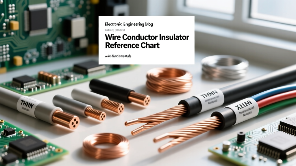
Wiring Implication: Because the current is low, we only need 12 AWG THHN copper wire (or 14 AWG, though 12 AWG is preferred for voltage drop mitigation on motor loads). Additionally, AC arcs naturally extinguish themselves 120 times a second as the sine wave crosses the zero-voltage line, making standard thermal-magnetic AC breakers highly effective and compact.
Expert Insight: When working with AC mains, always remember that the stated voltage (e.g., 120V or 240V) is the Root Mean Square (RMS) value. The actual peak voltage of a 120V AC circuit is approximately 170V ($120 \times \sqrt{2}$). Your wire insulation and component dielectrics must be rated to withstand this peak voltage, not just the RMS average.
Wiring Implications: Skin Effect vs. Uniform Current Density
One of the most fascinating physical differences between AC and DC is how electrons distribute themselves across the cross-section of a wire.
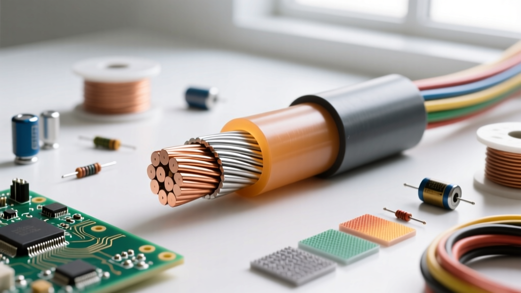
In a DC circuit, current density is uniform. Every copper strand in a stranded wire, and the very center of a solid core wire, carries an equal share of the electrons. The entire circular mil area of the conductor is utilized.
In an AC circuit, a phenomenon known as the skin effect occurs. The rapidly changing magnetic fields generated by the alternating current induce eddy currents that push the electron flow toward the outer perimeter (the "skin") of the conductor. As detailed in advanced electrical theory resources like All About Circuits, the skin effect is negligible at 60Hz for wires smaller than 1/0 AWG. However, for massive busbars or high-frequency AC (like the output of a high-frequency inverter or radio transmitter), the center of the conductor becomes virtually useless, prompting engineers to use hollow copper tubing or Litz wire to maximize surface area.
Component Behavior: Reactance in AC vs. DC
Passive components behave radically differently depending on the current type. Understanding this is crucial when designing filters or repairing power supplies.
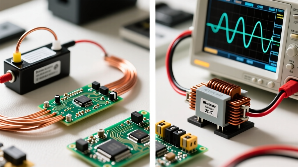
- Capacitors: In a DC circuit, a capacitor charges to the source voltage and then blocks all further current flow (acting as an open circuit). In an AC circuit, the constant reversal of voltage causes the capacitor to continuously charge and discharge, effectively allowing AC to "pass through." This is why capacitors are used as coupling components in audio amplifiers and as decoupling filters to shunt high-frequency AC noise to ground in DC logic boards.
- Inductors (Coils): Inductors resist changes in current. In a steady DC circuit, an inductor acts merely as a low-resistance piece of wire. In an AC circuit, the inductor constantly fights the changing current, presenting a frequency-dependent resistance called inductive reactance ($X_L = 2\pi fL$). This makes inductors ideal for AC chokes and ballasts.
Troubleshooting AC vs. DC Circuits with a Digital Multimeter
When diagnosing a faulty circuit, misidentifying the current type can lead to false readings or damaged equipment. Using a True-RMS multimeter, such as the industry-standard Fluke 87V, requires specific settings.
- Measuring DC: Set the dial to V with the straight line and dashed line symbol ($V_{DC}$). If you measure a 12V battery, the screen will read a steady 12.4V to 12.8V. If you accidentally use this setting on an AC wall outlet, the meter will likely read 0.0V or display an erratic, nonsensical number because the meter is attempting to average the positive and negative halves of the sine wave, which cancel each other out.
- Measuring AC: Set the dial to V with the wavy line symbol ($V_{AC}$). The meter's internal rectifier calculates the RMS heating value of the waveform. If you probe a DC battery with the AC setting, a high-quality True-RMS meter will block the DC offset and read 0.0V (or the AC ripple voltage, which should be near zero on a healthy battery).
Summary Comparison Matrix
| Feature | Direct Current (DC) | Alternating Current (AC) |
|---|---|---|
| Electron Flow | Unidirectional, constant | Bidirectional, oscillating |
| Standard Frequency | 0 Hz (Steady state) | 50 Hz or 60 Hz (Mains) |
| Wire Sizing Factor | Requires thicker wires for high power (High I) | Allows thinner wires for high power (High V, Low I) |
| Conductor Utilization | Full cross-section (Uniform density) | Skin effect at high frequencies/large gauges |
| Arc Extinguishing | Difficult; requires specialized DC breakers | Natural zero-crossing extinguishes arcs |
| Common Sources | Batteries, Solar Panels, Rectifiers | Alternators, Grid Generators, Inverters |
Mastering the fundamental differences between these two forms of electricity is not just an academic exercise. Whether you are calculating circular mils for a battery bank or selecting the correct dielectric for an AC motor run capacitor, recognizing the unique example of direct current and alternating current in your specific application ensures your projects are safe, efficient, and built to last.