Learning wire diagrams is essential for electricians, automotive technicians, industrial maintenance staff, and DIY electronics enthusiasts. This guide delivers a proven, sequential approach to mastering schematic interpretation—from recognizing basic symbols like resistors (IEC 60617-2) and relays (EN 61812-1) to decoding complex control circuits used in Ford F-150 powertrain modules or Siemens S7-1200 PLC systems. You’ll learn how to interpret conductor sizing (e.g., 14 AWG = 2.08 mm², rated for 15 A at 30°C per NEC Table 310.16), apply UL 508A color conventions (black for ungrounded AC, blue for DC negative), and verify continuity using a Fluke 87V multimeter. No prior electrical background is required—just curiosity, a ruler, and 30 minutes daily.
Why Wire Diagrams Matter More Than Ever
Wire diagrams—also called wiring schematics or circuit diagrams—are the universal language of electrical systems. Unlike physical layouts or pictorial diagrams, they communicate functional relationships, signal flow, and interconnections with precision. In 2023, the U.S. Bureau of Labor Statistics reported over 725,000 electricians employed nationwide, with 93% relying on printed or digital schematics daily. Automotive OEMs like Toyota mandate that all certified technicians pass the Toyota Technical Education Network (T-TEN) schematic interpretation exam before servicing hybrid vehicles such as the Camry Hybrid (XV70). Similarly, industrial facilities operating Rockwell Automation ControlLogix systems require engineers to read ladder logic integrated with wiring diagrams for safety-critical functions like emergency stop circuits compliant with ISO 13850.
The consequences of misreading a diagram are tangible. In a 2022 incident documented by the National Fire Protection Association (NFPA), a technician reversed hot and neutral conductors on a 240 V HVAC unit because he misinterpreted the line designation on a Carrier Infinity system schematic—causing a ground fault that tripped breakers across three floors. Accurate diagram literacy prevents equipment damage, reduces troubleshooting time by up to 68% (per a 2021 Eaton Field Study), and ensures compliance with OSHA 1910.303(b)(2), which requires all electrical equipment to be installed “in accordance with the manufacturer’s instructions and the wiring diagram.”
Core Components of Every Wire Diagram
A wire diagram is not a photograph—it’s an engineered abstraction. Its purpose is clarity, not realism. Every professional-grade schematic contains five non-negotiable elements:
- Title block: Includes drawing number (e.g., “F-150_FEM_2023_REV4”), revision date, and author (Ford Motor Company uses ASME Y14.100-compliant title blocks).
- Legend or symbol key: Defines non-standard icons; e.g., a rectangle labeled “PCM” means Powertrain Control Module per SAE J1939-13 standard.
- Reference designators: Alphanumeric tags like “K1” (relay), “R7” (resistor), or “M3” (motor); per IPC-2612, these must be unique within each sheet.
- Conductor identification: Wires labeled “B/W” (black with white stripe) or “18 AWG GRN” (18-gauge green insulated conductor).
- Grounding points: Symbols per IEEE 315-1975: open triangle (chassis ground), solid triangle (earth ground), or inverted triangle (signal ground).
Ignore any diagram missing a legend or reference designators—it’s incomplete for professional use. For example, Siemens Desigo CC wiring schematics always include a dedicated “Symbol Index” sheet referencing EN 60617-2, while Honeywell Experion PKS P&IDs embed cross-references to IEC 61850-6 substation automation logic.
Standardized Symbols You Must Know First
Start with the 12 most frequent symbols used across automotive, industrial, and residential applications. Memorize them using flashcards or free tools like CircuitLab’s symbol quiz. These appear in >90% of entry-level schematics:
- Resistor: Zigzag line (IEC 60617-2 symbol #04-01-01)
- Capacitor: Two parallel lines (polarized version adds + sign)
- SPST Switch: Single break in line with actuator line
- DC Power Source: Long line (+), short line (–)
- AC Power Source: Circle with sine wave inside
- Ground: Three horizontal decreasing-length lines
- Lamp: Circle with X inside
- Motor: Circle with letter “M”
- Transformer: Two parallel coils with dots indicating polarity
- Relay Coil: Rectangle labeled “K1”, “CR2”, etc.
- Normally Open (NO) Contact: Break in line with diagonal arrow pointing toward contact
- Fuse: Straight line with rectangle centered (UL 248-1 standard shape)
Note: Symbol orientation matters. A relay coil drawn horizontally versus vertically changes no function—but its associated contacts must align physically on the same page per ANSI/IEEE 91-1984. Misalignment is a red flag for outdated or amateur documentation.
Decoding Conductor Specifications
Wires aren’t just lines—they’re engineered components with defined physical properties. Every conductor label encodes size, insulation type, voltage rating, and temperature tolerance. Here’s how to decode real-world examples:
On a 2022 BMW i4 G26 high-voltage battery service manual, you’ll see “6 mm² ORANGE HTR 600V 125°C”. Breaking it down: “6 mm²” is cross-sectional area (equivalent to 10 AWG per ASTM B258-22), “ORANGE” denotes high-voltage DC circuit per ISO 6469-3, “HTR” means heat-resistant silicone rubber (UL AWM 20942), “600V” is dielectric strength, and “125°C” is maximum continuous operating temperature.
In contrast, a Schneider Electric TeSys D contactor wiring diagram lists “1.5 mm² PVC 300/500V 70°C”—meaning standard thermoplastic insulation suitable for general-purpose control circuits. The key is matching conductor specs to application demands: NEC Article 400.5(A)(1) requires 12 AWG minimum for branch circuits feeding 20 A loads, while SAE J1128 mandates 10 AWG minimum for automotive 12 V starter circuits.
| AWG Size | mm² Equivalent | Max Ampacity (NEC 310.16, 75°C) | Common Applications |
|---|---|---|---|
| 18 | 0.82 | 7 A | Doorbell wiring, sensor inputs (Allen-Bradley 1769-IF4) |
| 14 | 2.08 | 15 A | Lighting circuits, HVAC control (Carrier Infinity 26VS) |
| 12 | 3.31 | 20 A | Receptacle circuits, compressor leads (Trane XV20i) |
| 10 | 5.26 | 30 A | EV charger feeders (Tesla Wall Connector Gen3) |
| 6 | 13.3 | 65 A | Main service entrance, solar inverter output (Enphase IQ8+) |
Always verify conductor sizing against both load current and voltage drop. For a 24 V DC solenoid valve drawing 1.2 A over a 15 m run, using 18 AWG causes 3.7 V drop (exceeding the 10% rule), so 16 AWG (1.31 mm²) is required per IEEE 142-2020 Annex C calculations.
Color-Coding Standards: Global Rules & Critical Exceptions
Color coding reduces human error—but standards vary by region and application. Never assume black = hot. In North America, NEC 200.6 governs grounded conductor (white or gray) and equipment grounding conductor (green, green/yellow, or bare) identification. Ungrounded conductors may be any color except white, gray, or green. Yet in automotive wiring, SAE J1128 specifies red for battery positive, black for chassis ground, and yellow for ignition-switched power—regardless of AC/DC context.
Industrial control panels follow UL 508A Section 42.3: black for AC line voltage, blue for DC control circuits (24 VDC common), orange for DC power supplies, and brown for AC control power. But here’s the critical exception: in hazardous locations (Class I, Division 1), NFPA 70E 130.5(E) prohibits reliance solely on color—requiring additional labeling like “24 VDC – IS” (intrinsically safe) adjacent to terminals.
Real-World Diagram Walkthrough: Ford F-150 Instrument Cluster
Let’s apply concepts to an actual schematic: 2021 Ford F-150 instrument cluster wiring (Wiring Diagram 14-12, Rev. C). Locate sheet “IC-CLUSTER-POWER”. First, check the title block: drawing number “WIR-2021-F150-IC-001412”, revision “C”, date “2020-09-15”. Next, find the legend—note “GND” means chassis ground per Ford ESD-1100 standard, and “B+” is battery positive (12.6 V nominal).
Trace the power path: B+ enters at connector C111 pin 1 → fuse F32 (10 A) → relay K102 coil (pin 86) → ground via G102. When K102 energizes, its NO contacts (pins 30→87) route power to cluster backlight LEDs. Measure voltage drop across R23 (a 100 Ω current-limiting resistor) using Ohm’s Law: if LED draws 20 mA, expected drop is 2.0 V (V = I × R = 0.02 × 100). A reading of 0 V indicates open resistor; 12 V indicates shorted LED.
Now examine conductor labels: “16 BRN/WHT” means 16 AWG (1.31 mm²), brown with white stripe—confirming SAE J1128 ignition-switched circuit. Cross-reference with Ford’s Wiring Color Code Chart: BRN/WHT = “Ignition On, Engine Off” supply. If the cluster backlight fails but other functions work, this wire is the prime suspect.
Hands-On Practice Strategy: Build Your First Test Circuit
Reading diagrams without building is like studying swimming without water. Start simple: replicate a 3-wire thermostat circuit (common in Honeywell RTH9580WF). You’ll need:
- Honeywell RTH9580WF thermostat (supports 24 VAC heating/cooling)
- 24 VAC transformer (Tripp Lite SP-24-40, 40 VA)
- SPST toggle switch (Leviton 1271-I)
- 12 AWG THHN wire (black, red, white)
- Fluke 87V multimeter (true RMS, CAT III 1000 V)
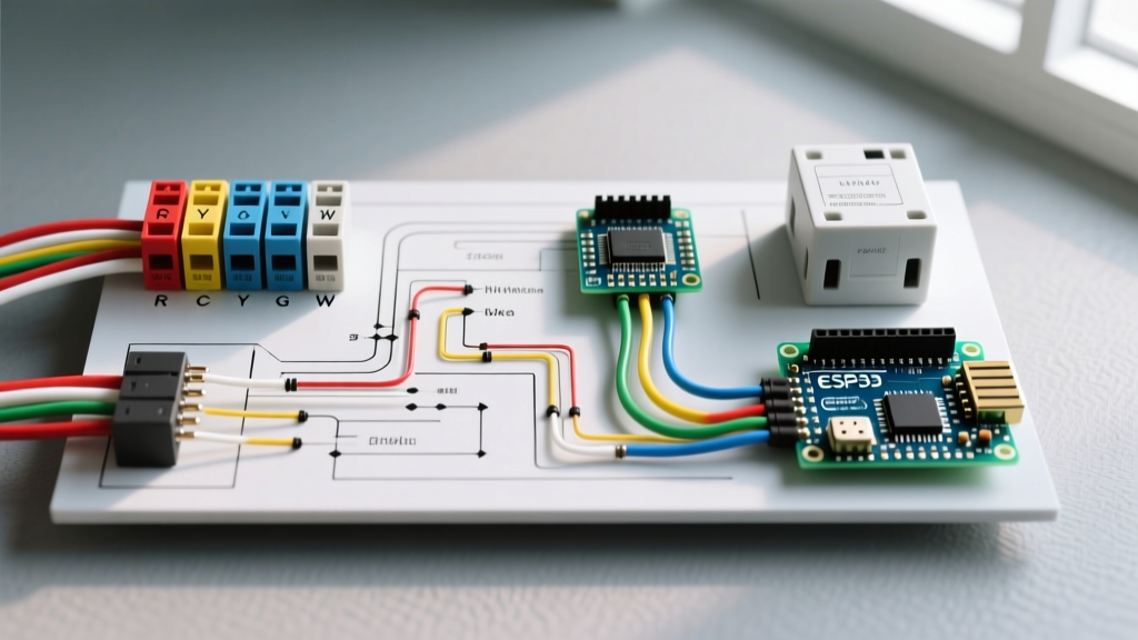
Follow the Honeywell installation manual diagram (page 12, Fig. 3A). Wire the transformer secondary: black to R (power), red to W (heat call), white to C (common). Connect the switch between W and C to simulate furnace demand. Power on and verify 24–28 VAC between R–C with no load; then 0 V between W–C when switch is open, and 24 V when closed. This validates your ability to trace power flow, identify control loops, and measure under load.
After mastering this, advance to a dual-contactor motor starter (Allen-Bradley 509-DP30). Use the 509-DP30 wiring diagram (Bulletin 509-UM001, p. 24) to wire overload protection, auxiliary contacts, and start/stop stations. Time yourself: professionals complete this wiring in ≤18 minutes. If you take >35 minutes, revisit symbol recognition and conductor labeling drills.
Free & Low-Cost Learning Resources
Don’t pay for theory—leverage authoritative free materials:
- NFPA 70 (NEC) Free Access: Download the full 2023 NEC handbook at nfpa.org/70 (includes Annex D examples with annotated diagrams).
- Siemens S7-1200 System Manual: Chapter 4.3 “Electrical Connection Diagrams” includes full-color schematics with I/O addressing tables (download from support.industry.siemens.com).
- Ford Wiring Diagrams Portal: ford.com/support/wiring-diagrams (requires free account; includes 2020–2023 F-150, Mustang Mach-E, and Transit schematics).
- Open-Source Simulator: use CircuitJS (falstad.com/circuit) to build and simulate circuits from real diagrams—e.g., input the Ford K102 relay circuit and toggle inputs to watch contact states change.
Avoid YouTube tutorials without timestamps or source citations. Instead, use the U.S. Department of Labor’s O*NET OnLine (onetonline.org) to search “Electrical Drafter” or “Automotive Technician” and review the “Tools & Technology” section—this lists exact software (AutoCAD Electrical, ETAP) and standards (ANSI/ASME Y14.15) employers require.
Measuring Progress: Milestones & Validation
Track progress using objective benchmarks—not subjective “I feel better.” After 30 days of consistent practice (30 minutes/day, 5 days/week), you should reliably achieve these milestones:
- Identify all 12 core symbols in <3 seconds each (time yourself with flashcards).
- Decode conductor labels like “10 AWG RED PVC 600V 90°C” without reference.
- Trace power flow from source to load in a 12-component automotive diagram (e.g., Toyota Camry 2022 headlight circuit) in ≤4 minutes.
- Calculate voltage drop for a 24 VDC 2 A circuit over 8 m using 14 AWG wire (answer: 0.48 V; acceptable per 3% rule).
- Build and test a 3-wire HVAC control circuit matching the Honeywell schematic with zero errors.
Validate skills using industry exams: the ETA (Electronic Technicians Association) offers the Certified Electronics Technician (CETa) exam ($195), which includes a 20-question schematic interpretation section. Passing score is 70%; average first-time pass rate is 58%, proving rigor. Alternatively, take the free Siemens S7-1200 Wiring Basics micro-certification (requires registration at siemens.com/s71200-training).
Remember: proficiency isn’t about memorizing every symbol. It’s about developing pattern recognition—the ability to spot a ground loop in a 50-page Rockwell Automation Panelview schematic by noticing duplicate GND symbols on unrelated subsystems, or identifying a missing fuse symbol before the load in a Schneider Electric Altivar drive diagram. That skill comes from deliberate, repeated exposure to real schematics—not generic illustrations. Start today with the Ford F-150 diagram. Print page IC-CLUSTER-POWER. Grab a highlighter. Trace one wire end-to-end. Then do it again tomorrow with a different circuit. In 30 days, you’ll read diagrams like a native speaker reads text—without translation.
Troubleshooting Pitfalls to Avoid
New learners consistently make three avoidable errors:
1. Confusing schematic flow with physical layout. A wire shown as a straight line from left to right may physically snake through a 3 m conduit with two 90° bends. Always consult the physical harness routing diagram (e.g., Ford’s “Harness Routing Manual”) alongside the schematic.
2. Assuming all grounds are equal. Chassis ground (GND), signal ground (SGND), and earth ground (EGND) serve different purposes. Connecting SGND to chassis in a PLC analog input module (e.g., Allen-Bradley 1769-IF4) induces 60 Hz noise—verified by measuring >10 mV AC on the 4–20 mA loop with a Fluke 87V.
3. Ignoring revision history. A 2019 Ford F-150 diagram (Rev. A) shows the heated seat module powered via fuse F24. The 2021 revision (Rev. C) moves it to fuse F37 due to added memory functions. Using the wrong revision causes misdiagnosis. Always check the revision block—never rely on file names like “F150_WIRING.pdf”.
When stuck, use the “3-Point Verification Rule”: confirm any connection at three independent points—(1) schematic symbol, (2) conductor label, and (3) physical terminal marking. If one disagrees, the document or component is faulty. Document discrepancies in a log: “2021 F-150 IC-CLUSTER-POWER Rev. C, C111 pin 1: schematic says ‘B+’, physical wire is brown, but multimeter reads 0 V → check fuse F32.” This habit separates technicians from troubleshooters.
Mastery begins with discipline—not inspiration. Set a timer. Open a real schematic. Highlight one wire. Check its specs. Trace its path. Repeat. In 90 days, you’ll interpret Siemens Desigo CC fire alarm interfaces or Tesla Model Y battery management schematics with confidence. The diagrams won’t change. You will.