
Introduction: The Quest for the Perfect Shield Termination
In the intricate world of cable harness manufacturing and avionics, terminating a braided cable shield to a ground wire is a critical process. For decades, this was a painstaking manual task prone to human error and thermal damage. Today, sleeve soldering—the use of heat-shrinkable tubing pre-loaded with precise rings of solder and flux—is the undisputed industry standard. But how did we get here? Understanding the history and evolution of sleeve soldering not only provides a fascinating look into materials science but also informs how professionals should select and apply these components in 2026.
'The transition from hand-soldering to preform solder sleeves represents one of the most significant leaps in wire harness reliability, reducing thermal exposure to sensitive dielectrics by over 70%.'
— Journal of Electronic Manufacturing, Historical Review of Interconnects
The Dark Ages: Hand-Soldering Shield Braids (Pre-1980s)
Before the commercialization of solder sleeves, terminating a coaxial cable or a multi-conductor shielded cable was an art form that relied heavily on the technician's manual dexterity. The traditional method involved several labor-intensive steps:
- Stripping and Combing: The outer jacket was stripped, and the metallic braid was 'combed' out using specialized picks.
- Twisting: The braid was twisted into a tight 'pigtail'.
- Fluxing: The pigtail was dipped in liquid rosin flux.
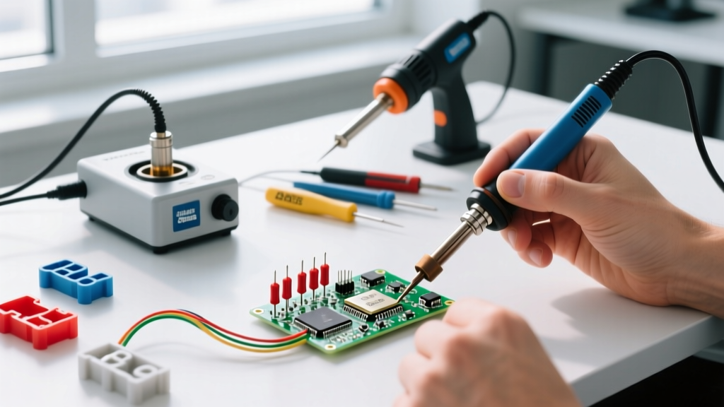
- Hand-Soldering: A technician would use a 40W to 60W soldering iron to tin the pigtail, then solder it to a separate ground wire.
Critical Failure Modes of the Old Method
This manual process was fraught with failure modes. The most common was thermal damage. PTFE (Teflon) and other high-performance dielectrics are sensitive to prolonged heat. A technician holding a 350°C iron against a braid for 10 seconds could easily melt the inner insulation, causing a short circuit. Furthermore, inconsistent flux application led to cold solder joints, and excess flux residue left behind corrosive chemicals that degraded the connection over time.
The Raychem Revolution: Birth of the Solder Sleeve (1980s-1990s)
The paradigm shifted in the late 1970s and early 1980s with the innovations of the Raychem Corporation (now part of TE Connectivity). Raychem had already pioneered radiation-crosslinked polymers, which allowed plastics to 'remember' their original shape and shrink when heated. Engineers realized they could combine this heat-shrink technology with pre-measured rings of solder and interior flux coatings.
The resulting product, trademarked as the SolderSleeve, revolutionized the industry. When a heat gun was applied to the sleeve, the polymer shrank, forcing the flux and solder rings into intimate contact with the wire braid. As the temperature reached the solder's melting point, the solder flowed, creating a perfect, consistent fillet. The shrinking polymer simultaneously provided mechanical strain relief and environmental sealing.
To explore the modern iterations of these pioneering products, engineers frequently reference TE Connectivity's solder sleeve lineup, which still dominates the aerospace and defense sectors today.
The RoHS Shift and Modern Metallurgy (2006-2026)
The next major evolutionary hurdle for sleeve soldering was the Restriction of Hazardous Substances (RoHS) directive. For decades, the industry relied on Sn63/Pb37 (Tin/Lead) solder, which melts at a forgiving 183°C (361°F). When lead was banned from commercial electronics, manufacturers had to transition to lead-free alloys, primarily SAC305 (96.5% Tin, 3.0% Silver, 0.5% Copper).
The Thermal Challenge of Lead-Free Sleeves
SAC305 melts at 217°C (422°F). This 34°C increase in melting temperature forced a redesign of the heat-shrink polymers. Standard polyolefin sleeves would melt, burn, or become brittle before the lead-free solder could flow. This led to the development of advanced fluoropolymers and high-temperature polyolefins capable of withstanding shrink temperatures up to 175°C and soldering temperatures exceeding 250°C without degrading.
2026 Buyer’s Matrix: Choosing the Right Solder Sleeve
As of 2026, the market offers highly specialized sleeves for distinct environments. Selecting the wrong material is a primary cause of field failures. Below is a comparison matrix to guide your procurement:
| Material / Alloy | Solder Melt Temp | Sleeve Shrink Temp | Best Application | 2026 Avg Cost (per 100) |
|---|---|---|---|---|
| Polyolefin / Sn63 (Leaded) | 183°C | 120°C | Legacy military, non-RoHS repair | $25.00 |
| Polyolefin / SAC305 (Lead-Free) | 217°C | 125°C | Commercial electronics, RoHS harnesses | $32.00 |
| PVDF / Sn10/90 (High Temp) | 220°C | 175°C | Aerospace, engine bay, high-vibration | $85.00 |
| Dual-Wall Sealant / SAC305 | 217°C | 125°C | Marine, outdoor, waterproof enclosures | $48.00 |
Executing the Perfect Joint: Modern Best Practices
Despite the elegance of the design, sleeve soldering still requires precise thermal management. Modern technicians use calibrated, forced-air heat guns (such as the Master Appliance HG-501B or Hakko FX-950 series) rather than open flames or uncalibrated wands.
Step-by-Step Execution Guide
- Preparation: Strip the cable jacket and comb the braid back 360 degrees. Do not twist the braid; leave it flared to allow the solder ring to seat properly.
- Positioning: Slide the sleeve over the ground wire, insert the flared braid and ground wire into the sleeve, and center the preform solder ring directly over the braid.
- Initial Heat: Apply hot air at 350°C (662°F) from a distance of 1 inch. Rotate the cable continuously to ensure even polymer shrinkage.
- Flow Phase: Once the sleeve is tight, focus the heat directly on the solder ring. Watch for the solder to flash from dull to shiny and flow outward.
- Cooling: Remove heat immediately after the solder flows. Hold the cable still for 5-8 seconds. Moving the wire while the solder is in a plastic state will cause a disturbed joint (a critical defect).
Inspection Criteria: What the Standards Demand
In professional environments, visual inspection is governed by strict criteria. According to the IPC/WHMA-A-620 standard, a target condition for a solder sleeve termination requires:
- The solder ring must be fully melted and visible as a continuous fillet at both ends of the ring.
- The heat-shrink insulation must be fully recovered with no signs of scorching, melting, or burning.
- There must be no exposed wire strands outside the sleeve.
Similarly, NASA-STD-8739.3 mandates that the solder must wet the shield and the ground wire, forming a smooth, concave fillet. Any evidence of 'solder balling' (where the solder forms isolated spheres instead of a continuous ring) is grounds for immediate rejection and rework.
Common Failure Modes in Modern Sleeve Soldering
Even with advanced 2026 materials, technicians encounter specific edge cases:
1. Flux Boil-Off (Solder Balling)
Cause: Applying heat too aggressively or too close to the sleeve. The internal flux reaches its boiling point and vaporizes before the solder ring melts, blowing the molten solder into isolated balls.
Solution: Use a wider airflow nozzle and increase the distance to the workpiece, allowing the thermal mass of the wire to bring the solder to melting temperature gradually.
2. Incomplete Shrinkage
Cause: Moving to the next joint before the polymer has fully cross-linked and recovered. This leaves a loose sleeve that provides no strain relief.
Solution: Heat until the sleeve is optically tight against the wire contours, then allow the 5-second cooling period.
3. Thermal Degradation of the Dielectric
Cause: Using a high-temperature PVDF sleeve on a cable with a low-melt PVC inner jacket. The 175°C shrink temperature of the sleeve melts the inner wire insulation.
Solution: Always cross-reference the sleeve's shrink temperature with the cable jacket's maximum thermal rating before procurement.
Conclusion
The evolution of sleeve soldering from messy, hand-wrapped pigtails to precision-engineered, RoHS-compliant preforms is a testament to the relentless pursuit of reliability in electrical engineering. By understanding the metallurgical shifts and adhering to modern IPC inspection criteria, technicians and procurement teams can ensure their shield terminations withstand the rigorous demands of modern electronics, whether in a commercial server rack or a deep-space probe.