
Bridging the Gap: Hobbyist vs. Industrial Soldering
Most beginner soldering projects found online focus solely on making an LED blink or assembling a simple DIY clock. While these are great for basic familiarization, they completely ignore the rigorous demands of industrial manufacturing, automotive electronics, and aerospace avionics. In a professional environment, a solder joint is not just an electrical connection; it is a structural, thermal, and metallurgical bond that must survive thermal cycling, vibration, and years of operational stress.
If your goal is to transition from a hobbyist to an electronics manufacturing technician, or if you simply want your DIY builds to achieve commercial-grade reliability, you must approach your early practice with an industry mindset. This guide reimagines traditional beginner soldering projects through the lens of real-world industry applications, focusing on the exact techniques, tooling, and inspection criteria used by certified professionals in 2026.
The IPC-A-610 Standard: Your Blueprint for Quality
Before picking up an iron, you must understand the language of industrial quality. The IPC-A-610 (Acceptability of Electronic Assemblies) is the globally recognized standard for soldered joints. It categorizes assemblies into three classes:
- Class 1 (General Electronic Products): Consumer goods where functionality is the only requirement (e.g., cheap toys).
- Class 2 (Dedicated Service Electronic Products): Products requiring extended life and performance, such as automotive ECUs and industrial controllers. Cosmetic defects are allowed if they don't affect reliability.
- Class 3 (High-Performance Electronic Products): Mission-critical systems like aerospace, medical life-support, and military hardware. Zero downtime is acceptable, and joints must meet strict geometric and metallurgical criteria.
The projects below are designed to train your muscle memory to consistently achieve Class 2 and Class 3 standards.
Metallurgy 101: Choosing the Right Alloy for the Job
Industry technicians do not just grab 'solder.' They select alloys based on thermal profiles. For your beginner projects, you will primarily encounter two alloys:
- Sn63/Pb37 (Tin/Lead): This is a eutectic alloy, meaning it melts and freezes at exactly the same temperature (183°C / 361°F). It has no 'pasty' phase, making it incredibly forgiving for beginners and ideal for aerospace applications where lead is still permitted due to its resistance to tin whiskers.
- SAC305 (96.5% Sn, 3.0% Ag, 0.5% Cu): The industry-standard lead-free alloy. It has a solidus of 217°C and a liquidus of 220°C. This 3-degree 'pasty' range means the solder is partially solid and partially liquid during cooling. Moving the component during this phase creates a catastrophic 'disturbed joint'.
4 Beginner Soldering Projects for Industry Applications
Project 1: Through-Hole Resistor Network (Focus: Wetting & Fillets)
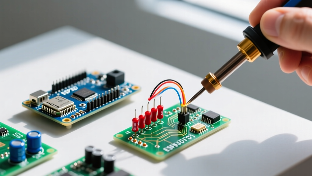
The Scenario: Populating a through-hole printed circuit board (PCB) is the foundation of all electronics assembly. In industrial settings, poor wetting leads to high contact resistance and eventual thermal failure.
The Execution:
- Use a 0.031" (0.8mm) diameter Sn63/Pb37 rosin-core wire (e.g., Kester 44).
- Set your iron to 315°C (600°F).
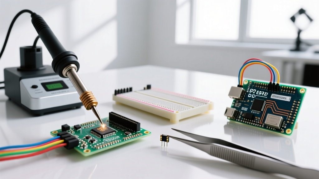
- Insert a 1/4W carbon film resistor into a fiberglass PCB.
- The Technique: Apply the iron tip so it simultaneously touches the component lead and the PCB pad. Count to two. Feed the solder wire into the joint, not the iron tip. Remove the solder, then remove the iron.
- Inspection Criterion: According to NASA Workmanship Standards, a Class 3 joint must exhibit a smooth, concave fillet with a wetting angle of less than 90 degrees. The solder must visibly flow up the lead, forming a continuous meniscus.
Project 2: Wire-to-Board Terminal Block (Focus: Mechanical Strain)
The Scenario: Automotive and industrial control panels rely heavily on wire-to-board connections. Vibration can easily snap a poorly soldered wire.
The Execution:
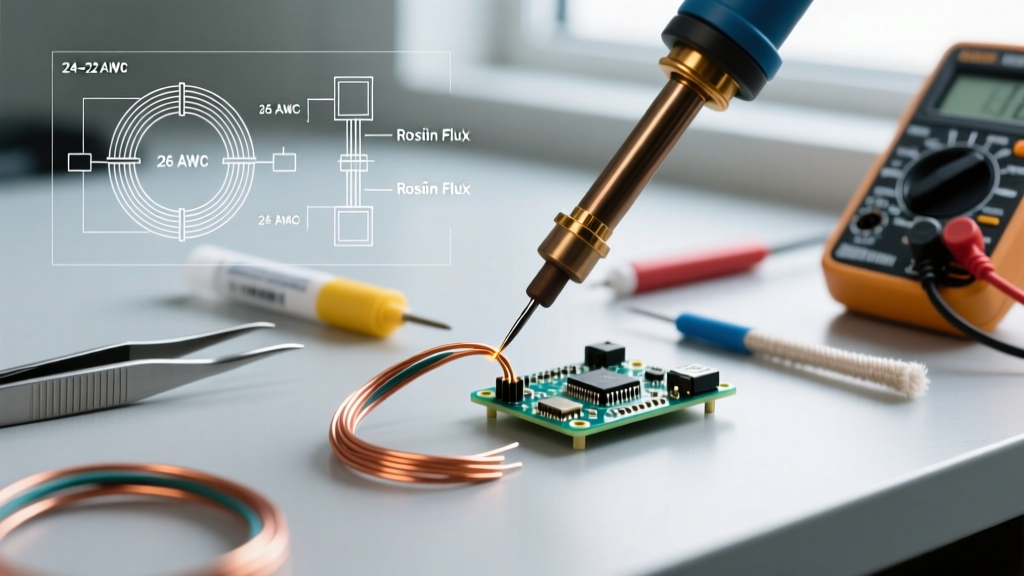
- Strip exactly 1/4" (6mm) of insulation from an 18 AWG stranded wire. Never nick the copper strands, as this creates a stress riser that will snap under vibration.
- Twist the strands tightly and apply a light coat of liquid flux (e.g., Kester 951).
- Tin the wire with a thin layer of solder. The solder should wick up to the insulation jacket but never under it. Solder under the insulation makes the wire rigid and prone to snapping at the flex point.
- Solder the tinned wire into a heavy-duty PCB terminal block.
- Inspection Criterion: The wire strands must be fully encapsulated but still discernible under the solder. There should be no 'birdcaging' (strands poking out) and no solder wicking into the wire's flex zone.
Project 3: TO-220 Transistor Heat Sink Assembly (Focus: Thermal Management)
The Scenario: Power electronics (motor drivers, power supplies) generate massive heat. Improper mounting of TO-220 packages to heat sinks leads to thermal runaway and component destruction.
The Execution:
Project 4: 0805 SMD LED Array (Focus: Surface Mount Transition)
The Scenario: Modern consumer electronics and IoT devices are 99% Surface Mount Device (SMD). Transitioning from through-hole to SMD is mandatory for industry relevance.
The Execution:
- Use 0.015" (0.4mm) SAC305 solder wire and a fine conical tip.
- Apply a thin layer of tacky no-clean flux (e.g., Amtech NC-559-V2-TF) to one PCB pad.
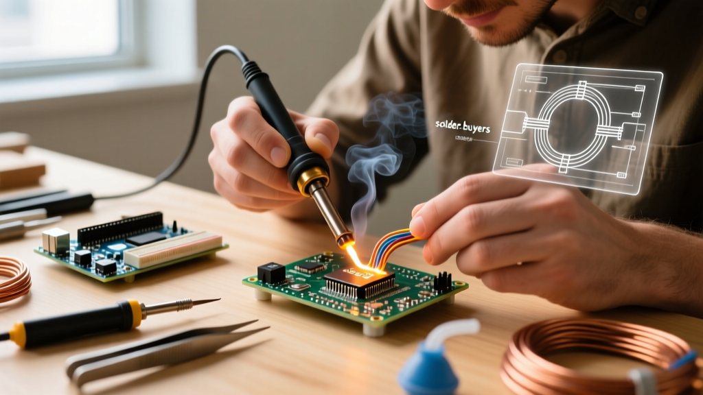
- Using fine-tipped ESD-safe tweezers, place the 0805 LED. Melt a tiny amount of solder on the first pad to 'tack' the component in place.
- Apply flux to the second pad, touch the iron to the pad and the component terminal simultaneously, and feed a microscopic amount of solder.
- Inspection Criterion: The solder should form a smooth, concave fillet on the side of the component. The component must be perfectly aligned with the PCB pads; any rotation or offset exceeding 25% of the pad width is a reject under IPC Class 2.
Industry-Standard Tooling for Beginners (2026 Buyer Matrix)
You cannot achieve Class 3 results with a $15 unregulated iron. Thermal recovery is the metric that separates hobbyist tools from industrial tools. When a cold component touches the tip, an industrial station dumps wattage instantly to maintain the setpoint.
| Station Model | Wattage | Temp Range | Price (2026) | Best Industry Application |
|---|---|---|---|---|
| Hakko FX-888D | 70W | 120°C - 480°C | $115 | General Through-Hole & Heavy Wire |
| Weller WES51 | 50W | 177°C - 454°C | $120 | Precision Analog & Aerospace TH |
| Pinecil V2 | 65W | 100°C - 450°C | $28 | Field Repair & SMD Prototyping |
| JBC CD-2BQF | 130W | 150°C - 450°C | $495 | High-Volume SMD & Multilayer PCBs |
Critical Failure Modes and Inspection
Industry technicians use 10x magnification loupes to inspect their work. Here are the most common failure modes beginners must learn to identify and avoid:
- Cold Joint: Appears grainy, dull, and bulbous. Caused by insufficient heat transfer. The solder did not reach its liquidus temperature, resulting in a high-resistance mechanical connection rather than a metallurgical bond.
- Disturbed Joint: Appears frosty or cracked. Caused by moving the component while the SAC305 solder was in its 3-degree 'pasty' phase during cooling. This compromises the crystalline structure of the joint.
- Icicle / Solder Ball: Excess solder that fails to wet the pad, often forming a sphere. Caused by oxidized pads, insufficient flux, or applying solder directly to the iron tip instead of the joint.
Fume Extraction and Safety Standards
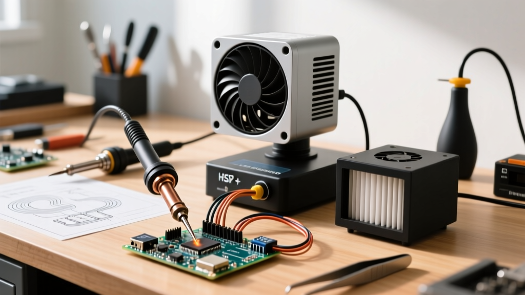
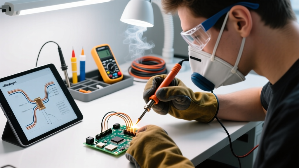
In industrial environments, solder fume management is not optional; it is a strict OSHA requirement. The rosin (colophony) core inside solder wire vaporizes at soldering temperatures, creating sub-micron particulate matter and volatile organic compounds (VOCs). According to the National Institute for Occupational Safety and Health (NIOSH), repeated exposure to rosin flux fumes is a leading cause of occupational asthma and contact dermatitis.
Actionable Advice: Never solder in a stagnant room. At a minimum, use an activated carbon fan filter (like the Hakko FA-400). For true industry compliance, invest in a HEPA-filtered fume extractor with an articulating arm positioned exactly 2 to 3 inches from the solder joint to capture the plume before it enters your breathing zone.
Final Thoughts on Building a Professional Portfolio
By treating your beginner soldering projects as industrial training exercises, you accelerate your path from amateur to professional. Document your progress by taking macro-photographs of your joints and comparing them against the IPC-A-610 visual standards. Mastering the metallurgy of eutectic alloys, the mechanical requirements of strain relief, and the thermal dynamics of SMD reflow will give you a massive advantage whether you are building a custom drone controller or applying for a technician role in the medical device sector.