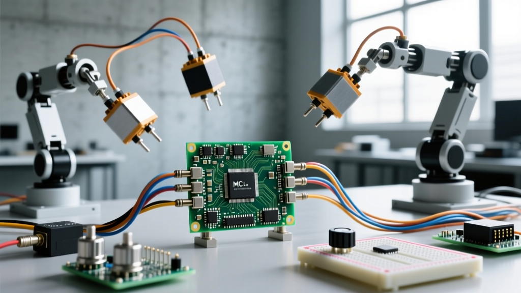

At the workbench, the question of what do servos do boils down to one core function: they provide precise, closed-loop angular position control. Unlike a standard DC motor that spins freely when voltage is applied, a hobby servo contains an internal potentiometer and a control board that constantly compares the output shaft's actual position to the incoming PWM (Pulse Width Modulation) signal. If the shaft is out of place, the internal H-bridge drives the motor to correct the error. This makes them the default actuator for robotic arms, camera gimbals, and RC steering linkages where knowing the exact angle is non-negotiable.
However, slapping a servo onto an ESP32 or Arduino without understanding its electrical demands is a fast track to brownouts and stripped gears. Below is a practical breakdown of how servos compare to other motors, how to wire them without frying your microcontroller, and how to size them for real-world mechanical loads.
Motor Type Selection: Which Actuator Fits Your Load Profile?
A common mistake in embedded design is treating steppers and servos as interchangeable. They are not. Steppers excel at holding position without feedback and moving in discrete micro-steps, but they lose torque rapidly at higher speeds and draw high current even when stationary. Servos deliver high torque at speed and only draw significant current when actively moving or fighting a load, but they are generally limited to 180° or 270° of rotation (unless modified).
| Motor Type | Torque Curve | Control Needs | Cost (Typical Hobby) | Best Use Case |
|---|---|---|---|---|
| Standard PWM Servo | High stall torque, maintains torque across rated speed. | 50Hz PWM signal (1-2ms pulse). Needs 5V-6V high-current BEC. | $10 - $25 (e.g., MG996R, DS3218) | Robotic joints, steering linkages, camera pans. |
| Stepper Motor | High holding torque, drops off sharply as RPM increases. | Step/Dir pulses via driver (A4988, TMC2209). Needs 12V-24V PSU. | $15 - $40 (e.g., NEMA 17 + TMC2209) | 3D printers, CNC routers, linear actuators. |
| Brushed DC Motor | Low torque at low RPM, peaks at mid-speed. Requires gearbox. | H-Bridge (L298N, DRV8871) for speed/direction. Open-loop. | $5 - $15 (with basic gearbox) | Drive wheels, conveyors, high-speed fans. |
| Smart Serial Servo | Similar to PWM, but includes thermal and load feedback. | UART/Half-duplex serial (Dynamixel protocol). 7V-12V. | $45 - $250 (e.g., Dynamixel XL430) | Advanced bipedal robots, multi-joint kinematics. |
If your application requires moving a specific weight to a specific angle and holding it there efficiently, the standard PWM servo is your component. If you need continuous, multi-revolution precision positioning, you need a stepper.
Servo Wiring, Terminals, and Microcontroller Integration
Standard hobby servos use a 3-pin JST connector. Misidentifying these terminals is the most common cause of dead microcontrollers. The pinout is universally standardized across major brands (Futaba, JR, Hitec), though wire colors vary slightly.
- Ground (GND): Usually Brown or Black. Must be tied to the microcontroller's GND and the power supply's GND to establish a common reference.
- Power (VCC): Usually Red. Requires 4.8V to 6.0V DC. Never connect this to the 5V pin of an Arduino or the 3V3 pin of an ESP32.
- Signal (PWM): Usually Orange, Yellow, or White. Accepts a 3.3V or 5V logic-level PWM signal. Connects directly to a GPIO pin.
Standard Arduinos use software interrupts for the
Servo.h library, which can cause micro-jitter if other interrupts (like I2C or WiFi) fire. The ESP32 features hardware LEDC (LED Control) PWM channels. When driving servos with an ESP32, use the hardware PWM API (setting frequency to 50Hz and resolution to 16-bit) to achieve rock-solid, jitter-free positioning. See the Espressif LEDC documentation for register-level details.
What Driver or Controller Does a Servo Demand?
A single micro servo (like an SG90) draws about 200mA and can be powered by a robust external 5V USB supply. However, standard metal-gear servos (like the MG996R) have a stall current of 2.5A. If you are driving more than two standard servos, your microcontroller's GPIO pins cannot source the current, and a standard breadboard power rail will melt.
For multi-servo rigs, you demand two things:
- A high-current BEC (Battery Eliminator Circuit) or Buck Converter: Rated for at least 5A continuous to handle simultaneous startup current spikes.
- An I2C PWM Driver: The PCA9685 16-channel servo driver is the industry standard. It offloads PWM generation from your microcontroller via I2C and provides screw terminals for high-current servo power injection.
Sizing Rule of Thumb and Worked Load Example
Servo torque is rated in kg-cm or oz-in, representing the stall torque—the maximum weight the servo can hold at a 1 cm (or 1 inch) radius from the shaft center before it stalls. Sizing Rule of Thumb: Always calculate your required torque and multiply by a minimum 2x safety factor to account for dynamic acceleration forces and mechanical friction.
Worked Example: Robotic Arm Gripper
Suppose you are building a robotic arm that needs to lift a 250g (0.25 kg) payload. The distance from the servo shaft (the elbow joint) to the center of mass of the payload is 18 cm.
- Calculate Base Torque: Torque = Force × Distance.
0.25 kg × 18 cm = 4.5 kg-cm. - Account for Arm Weight: The 3D-printed arm itself weighs 100g, with its center of mass at 9 cm.
0.10 kg × 9 cm = 0.9 kg-cm. - Total Static Load: 4.5 + 0.9 = 5.4 kg-cm.
- Apply Safety Factor: 5.4 kg-cm × 2.0 (dynamic factor) = 10.8 kg-cm required.
Based on this math, a standard 9 kg-cm servo will fail. You need to select a servo rated for at least 12 kg-cm, such as the DS3218 (20 kg-cm, ~$22) or the classic MG996R (10-13 kg-cm depending on the manufacturer, ~$12). For a comprehensive breakdown of servo mechanical limits, refer to the Pololu RC Servo Guide.
Recognizing Failure Signatures
Servos fail in distinct ways that tell you exactly what is wrong with your circuit or mechanical design:
- The Hum (Hunting): A continuous buzzing sound without movement means the internal potentiometer is dirty, the mechanical linkage is binding, or your PWM signal has noise/jitter causing the servo to constantly 'hunt' for the target position.
- Overheat: If the servo casing is too hot to touch, it is likely stalled against a physical hard stop while receiving a PWM signal demanding a different position. The internal motor is dumping all energy as heat. Cut power immediately or the internal PCB will melt.
- Stall and Strip: If the servo motor hums but the output shaft doesn't move under load, you have exceeded the stall torque. If you hear a grinding noise, the internal gears (often nylon in cheaper models) are stripping. Upgrade to steel or titanium gears for high-shock loads.
Frequently Asked Questions
What do servos do when they jitter or hum under load?
Jitter is almost always an electrical issue, while humming is mechanical. If the servo twitches randomly, your microcontroller's PWM signal is unstable (common with software PWM on Arduinos handling heavy serial loads) or your power supply has high ripple voltage. If it hums steadily, the mechanical load is binding, preventing the shaft from reaching the exact target angle, causing the internal H-bridge to rapidly pulse the motor back and forth across the target threshold.
What do continuous rotation servos do compared to standard 180-degree models?
A continuous rotation servo has had its internal physical hard stops removed and its potentiometer disconnected or replaced with a fixed voltage divider. Instead of mapping PWM pulse width to an absolute angle (e.g., 1.5ms = 90°), it maps pulse width to speed and direction (1.5ms = stopped, 1.0ms = full speed reverse, 2.0ms = full speed forward). They are excellent for simple drive wheels but offer zero positional feedback or holding torque.
What do smart serial servos do that standard PWM hobby servos cannot?
Smart servos (like the Dynamixel or Feetech SCS series) replace the simple PWM receiver with a microcontroller and a UART serial interface. This allows the host controller to daisy-chain dozens of servos on a single serial bus. More importantly, smart servos provide two-way telemetry: you can read back the exact present position, internal temperature, input voltage, and motor load in real-time. This allows your code to detect if a joint is stalled or overheating before physical damage occurs, a feature entirely absent in standard 3-pin PWM servos.


