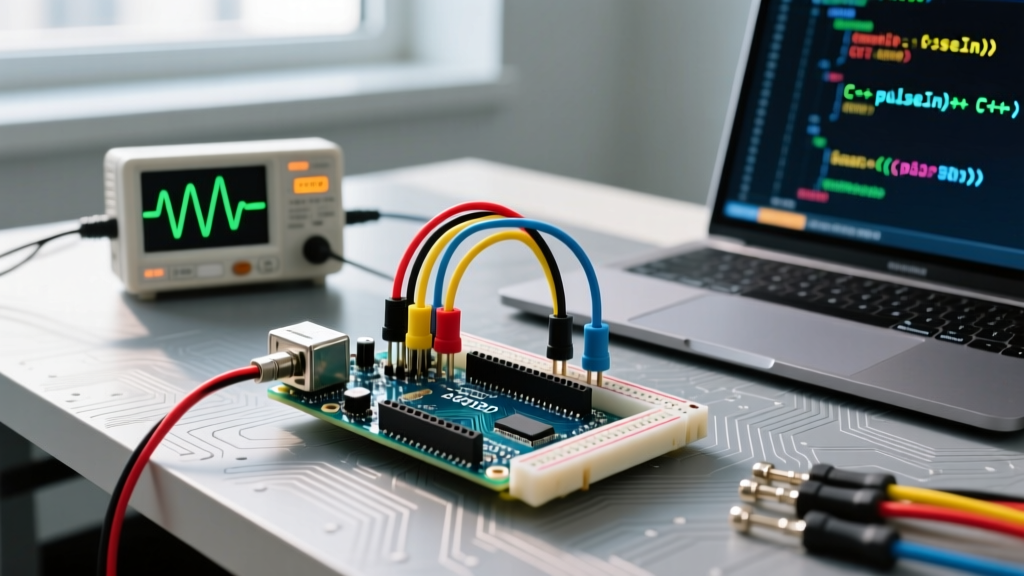
The Arduino Bluetooth module HC-05 is a Serial Port Profile (SPP) transceiver that bridges a microcontroller's local UART bus to a Bluetooth Classic 2.4GHz RF link. Out of the box, it acts as a transparent serial tunnel: bytes pushed to its TX/RX pins are broadcast over the air, and vice versa. While newer BLE (Bluetooth Low Energy) modules like the HM-10 or ESP32's native radio dominate low-power IoT, the HC-05 remains the bench standard for high-throughput, continuous serial streaming to Android devices, Windows PCs, and legacy automotive diagnostics.
To use it reliably, you must treat it as two distinct protocols: the local wired UART bus and the wireless Bluetooth SPP link. Failing to respect the physical layer requirements of the local UART bus is the primary reason builders fry their modules on the first power-up.
Bus Mechanics: UART vs. Bluetooth SPP
When designing your system, you must match the protocol to your distance, speed, and device count requirements. The HC-05 handles the translation between these two domains.
| Parameter | Local Bus (UART) | Wireless Bus (Bluetooth 2.0 SPP) |
|---|---|---|
| Wires / Medium | 4 (VCC, GND, TX, RX) | 2.4GHz RF (No physical wires) |
| Max Speed | Up to 1.38 Mbps (theoretical) Typically 9600 to 115200 baud |
~1 Mbps (actual throughput ~700 kbps) |
| Addressing | None (Point-to-Point hardware link) | 48-bit MAC Address (BD_ADDR) |
| Max Distance | ~15 meters (unshielded cable at 9600 baud) | ~10 meters (Class 2 radio, line-of-sight) |
| Device Count | 1 Master to 1 Slave | 1 Master to 1 Slave (Active SPP connection) |
Physical Layer: Wiring, Level Shifting, and Pull-Ups
The most common point of failure with the HC-05 is logic level mismatch. The module's internal CSR8645 chipset operates at 3.3V logic. While the HC-05's TX pin outputs 3.3V (which a 5V Arduino Uno safely reads as a logical HIGH), the RX pin is strictly 3.3V tolerant. Feeding 5V from an Arduino's TX pin directly into the HC-05's RX pin will degrade or instantly destroy the module's internal silicon.
The Voltage Divider Requirement:
You must step down the 5V TX signal to ~3.3V using a simple resistor divider. A 1kΩ resistor in series with the Arduino TX, and a 2kΩ resistor from the HC-05 RX to GND, yields 3.33V.
- Arduino TX (Pin 11) → 1kΩ Resistor → HC-05 RX
- HC-05 RX → 2kΩ Resistor → GND
- Arduino RX (Pin 10) → Direct wire → HC-05 TX
- Arduino 5V → HC-05 VCC (Module has an onboard 3.3V LDO regulator)
- Arduino GND → HC-05 GND
Pull-Up Requirements for AT Mode:
The HC-05 features an EN (or KEY) pin. To enter AT command mode for configuration, this pin must be pulled HIGH (3.3V) before the module receives power. If left floating, internal leakage can cause the module to randomly boot into data mode or fail to accept baud rate changes. Use a 10kΩ pull-up resistor to 3.3V, or wire it to a digital GPIO pin and drive it HIGH before initializing serial.
Minimal Working Exchange and Bus Debugging
Below is a minimal, robust exchange script using SoftwareSerial. This allows you to keep the hardware serial port (Pins 0/1) free for USB debugging with the Arduino IDE Serial Monitor.
#include <SoftwareSerial.h>

// Wiring: Arduino Pin 10 (RX) to HC-05 TX
// Wiring: Arduino Pin 11 (TX) through 1k/2k divider to HC-05 RX
SoftwareSerial BTSerial(10, 11);

void setup() {
  Serial.begin(9600);    // USB Debug Monitor
  BTSerial.begin(9600);  // HC-05 default data baud rate
  Serial.println('HC-05 Ready. Type to send to Bluetooth.');
}

void loop() {
  // Read from Bluetooth module, send to USB Serial Monitor
  if (BTSerial.available()) {
    Serial.write(BTSerial.read());
  }
  // Read from USB Serial Monitor, send to Bluetooth module
  if (Serial.available()) {
    BTSerial.write(Serial.read());
  }
}
The Classic Failures
When the bus refuses to communicate, 95% of issues fall into three categories:
- Baud Mismatch: The HC-05 defaults to 9600 baud in data mode, but switches to 38400 baud in AT command mode. If your
SoftwareSerial.begin()doesn't match the module's current state, you will see garbage characters or nothing at all. - Missing Pull-Up on EN/KEY: If you are trying to send AT commands but the module ignores them, the EN pin likely wasn't held HIGH during the power-on reset sequence.
- Address Clash / MAC Binding: The HC-05 doesn't use IP addresses, but it does use MAC binding. If a previous user hardcoded the module to bind to a specific phone's MAC address using
AT+BIND, it will reject pairing attempts from your device. Fix this by entering AT mode and issuingAT+ORGLto restore factory defaults.
How to Sniff and Debug the Bus
If your Arduino code is running but the Bluetooth link is dropping bytes, you need to isolate the fault domain. Use a USB-to-TTL FTDI adapter (set to 3.3V logic) to intercept the UART lines. Connect the FTDI RX pin to the HC-05 TX pin (alongside the Arduino RX pin). Open a secondary serial terminal (like PuTTY or CoolTerm) on the FTDI's COM port. This allows you to 'sniff' the exact bytes leaving the Bluetooth module in real-time, proving whether the RF link is dropping packets or if the Arduino's software buffer is overflowing. For microsecond timing issues, clip a logic analyzer (like a Saleae clone) to the TX/RX lines and decode the UART frames in PulseView to check for framing errors.
Arduino Bluetooth Module HC-05 FAQ
How do I change the default baud rate on the Arduino Bluetooth module HC-05?
You must enter AT command mode. Wire the EN/KEY pin to 3.3V, then power up the module (the LED will blink slowly, once every 2 seconds). Open your serial monitor at 38400 baud with 'Both NL & CR' selected. Send the command AT+UART=115200,0,0. The module should reply OK. Power cycle the module, and it will now communicate at 115200 baud in standard data mode. Refer to the Arduino SoftwareSerial documentation for limitations on high baud rates with software emulation.
Why is my Arduino Bluetooth module HC-05 blinking rapidly but refusing to pair?
A rapid, continuous blink (typically 2-5 times per second) indicates the module is in standard discoverable data mode, waiting for a connection. If your phone or PC sees the device but fails to pair, the issue is usually OS-level. Modern iOS devices do not support Bluetooth Classic SPP; they require BLE (use an HM-10 instead). Android and Windows support SPP, but Windows often requires you to pair via the legacy 'Bluetooth Devices' control panel rather than the modern Settings app. Ensure you are using the default PIN 1234 or 0000.
Can I use the Arduino Bluetooth module HC-05 with a 3.3V board like the ESP32 or Raspberry Pi Pico?
Yes, and it is actually much easier. Because the ESP32 and Pico natively output 3.3V logic on their GPIO pins, you do not need the 1k/2k voltage divider on the RX line. You can wire the microcontroller's TX pin directly to the HC-05 RX pin. Just ensure you power the HC-05 VCC pin with 5V (or 3.3V if your specific breakout board has a bypassed LDO, though 5V is safer for RF transmission stability) and share a common GND. For a deeper understanding of serial protocols across different logic families, review SparkFun's guide to serial communication.