
Project Overview: The Automated Auger Pet Feeder
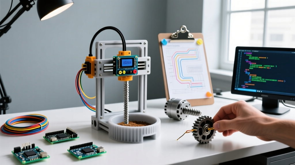
When exploring functional 3d print arduino projects, few builds offer the perfect intersection of mechanical engineering, electronics, and daily utility like an automated auger pet feeder. Commercial feeders often suffer from jammed kibble, unreliable Wi-Fi dependencies, and flimsy plastic gears. By designing and printing our own auger-driven dispensing system, we eliminate these failure points.
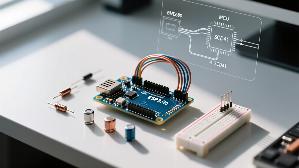
This step-by-step tutorial will guide you through building a robust, time-based pet feeder utilizing an Arduino Nano, a high-torque NEMA 17 stepper motor, and custom 3D-printed PETG components. We will cover precise slicer settings for food-adjacent parts, I2C real-time clock (RTC) integration, and firmware logic designed to detect and clear kibble jams automatically.
Bill of Materials (BOM) & Cost Breakdown
Before firing up your slicer, gather the following components. Pricing reflects average 2026 market rates for hobbyist electronics.
| Component | Specific Model / Details | Est. Cost (USD) |
|---|---|---|
| Microcontroller | Arduino Nano V3.0 (ATmega328P, USB-C variant) | $6.50 |
| Stepper Motor | NEMA 17 (17HS4401, 1.5A, 42oz-in torque) | $13.00 |
| Motor Driver | A4988 Stepper Driver Carrier with heatsink | $3.50 |
| Timekeeping | DS3231 Precision RTC Module (I2C) | $4.00 |
| Power Supply | 12V 2A Switching PSU (DC 5.5x2.1mm barrel) | $8.00 |
| Bearings | 608ZZ (8x22x7mm) - 2 required for auger support | $2.00 |
| Filament | Overture PETG (Hopper) & PolyLite PLA-Pro (Auger) | $25.00/kg |
| Hardware | M3 and M4 hex socket cap screws, nuts, heat-set inserts | $5.00 |
Total Estimated Build Cost: ~$42.00 (excluding bulk filament and hardware kit costs).
3D Printing Parameters for Functional & Food-Adjancent Parts
The success of mechanical 3d print arduino projects hinges on proper material selection and slicer configuration. The hopper and auger require distinct material properties.
Material Selection
- Hopper & Enclosure (Overture PETG): PETG offers superior moisture resistance and durability compared to PLA. While no raw 3D printed plastic is inherently 'food safe' due to layer line bacterial growth, PETG is chemically stable. Expert Tip: Coat the interior of the PETG hopper with a food-safe epoxy resin like Alumilite Clear to seal the micro-pores.
- Auger & Drive Gears (Polymaker PolyLite PLA-Pro): Standard PLA is too brittle for the shear stress of crushing kibble. PLA-Pro (or PLA+) offers the necessary impact resistance and prints with tighter dimensional accuracy for the auger threads.
Cura / PrusaSlicer Settings
- Nozzle Diameter: 0.4mm brass or hardened steel.
- Layer Height: 0.2mm for the auger (ensures smooth thread profile); 0.28mm for the hopper body (faster print, strong walls).
- Wall Line Count: 6 walls (2.4mm thickness) for the hopper base to handle the static load of 3kg of kibble without bowing.
- Infill: 15% Gyroid for the enclosure; 100% infill for the auger core and motor mount brackets.
- Supports: Use 'Tree Supports' with a 0.2mm Z-distance for the auger discharge chute overhangs to minimize scarring on the mating surfaces.
Step 1: Mechanical Assembly & Tolerance Management
Press-fitting bearings and motors into 3D printed parts is a common failure point in DIY automation. FDM printing inherently has a 0.1mm to 0.2mm dimensional variance depending on your extrusion multiplier.
Seating the 608ZZ Bearings
Design your motor mount and discharge bracket bearing seats at 21.9mm (for the 22mm outer diameter of the 608ZZ). Do not attempt to force the bearings in with a hammer, as PLA-Pro will shatter under sudden impact. Instead, use a bench vise with flat wooden blocks to apply slow, even pressure until the bearing seats flush against the printed shoulder.
Mounting the NEMA 17
Secure the NEMA 17 to the motor mount using four M3x8mm screws. Insert M3 brass heat-set inserts into the printed mount using a soldering iron set to 260°C. Apply gentle downward pressure until the insert is flush. This prevents the screws from stripping the plastic threads during motor vibration.
Step 2: Electronics Wiring & I2C Setup
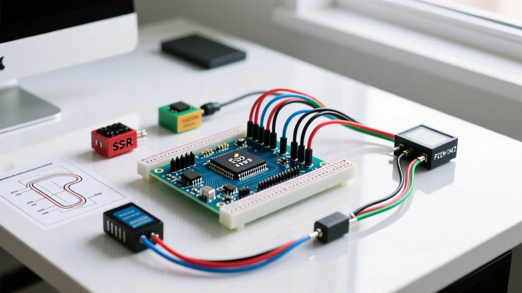
The wiring harness requires managing high-current stepper lines alongside sensitive 5V logic. Keep the stepper motor wires physically separated from the I2C RTC lines to prevent electromagnetic interference (EMI) from causing timekeeping errors.
| Arduino Nano Pin | Component | Function |
|---|---|---|
| D2 | A4988 STEP | Step Pulse Signal |
| D3 | A4988 DIR | Direction Control |
| D4 | A4988 ENABLE | Driver Power State |
| A4 (SDA) | DS3231 SDA | I2C Data Line |
| A5 (SCL) | DS3231 SCL | I2C Clock Line |
| 5V | DS3231 VCC | Logic Power (Do not use 3.3V) |
| GND | Common Ground | Shared Ground for 12V & 5V systems |
Critical Vref Calibration: Before connecting the NEMA 17, you must tune the A4988 current limit. Connect a multimeter to the Vref test point and the ground pin on the driver. Turn the brass potentiometer until you read 0.4V. This limits the current to ~1A per coil, providing ample torque to turn the auger while preventing the A4988 from triggering its thermal shutdown protection.
Step 3: Firmware Logic & Anti-Jam Routines
For the firmware, we rely on the AccelStepper library to manage acceleration profiles, preventing the stepper motor from stalling on startup. We also utilize the DS3231 precision RTC for accurate, offline timekeeping.
The most critical aspect of coding 3d print arduino projects that interact with physical bulk materials is handling edge cases—specifically, kibble bridging and auger jamming.
The 'Shake' Anti-Jam Routine
If the auger encounters a dense cluster of kibble, the stepper will skip steps. Since the A4988 lacks native stall detection without additional circuitry, we implement a software-based 'shake' routine. Before every scheduled full rotation (dispensing cycle), the code commands the motor to reverse 15 steps, pause for 200ms, and then proceed with the forward dispensing rotation. This breaks the static friction and collapses any 'bridges' formed by the kibble in the hopper throat.
// Anti-Jam Logic Snippet
stepper.setCurrentPosition(0);
stepper.moveTo(-15); // Reverse slightly to break kibble bridge
stepper.runToPosition();
delay(200);
stepper.moveTo(800); // Full forward rotation (approx 4 revolutions)
stepper.runToPosition();
Troubleshooting Common Failure Modes
Even with precise tolerances, real-world deployment of automated feeders introduces variables. Here is how to diagnose the most common issues:
- Issue: Motor hums but does not turn.
Cause: Vref is set too low, or acceleration in AccelStepper is too aggressive.
Fix: Increase Vref by 0.1V increments (max 0.6V for this setup) or lower thesetMaxSpeed()andsetAcceleration()parameters in your code. - Issue: RTC loses time when main power is disconnected.
Cause: CR2032 battery is dead, or the I2C pull-up resistors on the DS3231 module are conflicting with the Nano's internal pull-ups.
Fix: Verify battery voltage (should be >2.8V). If using a cheap clone DS3231 board, ensure you are using the appropriate I2C library that handles bus initialization gracefully. - Issue: PETG Hopper cracks near the motor mount.
Cause: Layer adhesion failure due to printing too cold or excessive part cooling fan.
Fix: Print PETG at 245°C nozzle / 80°C bed, and reduce the part cooling fan to 30% to maximize inter-layer bonding strength.
Final Thoughts on 3D Printed Automation
Building an auger-based pet feeder elevates your portfolio of 3d print arduino projects from simple desk toys to reliable household appliances. By respecting material science (using PETG for moisture barriers and PLA-Pro for shear strength), calibrating your stepper drivers properly, and writing defensive code that anticipates mechanical jams, you create a system that outperforms commercial alternatives. Always remember to test the feeder with a manual override button for at least 48 hours before trusting it to feed your pets while you are away.