The Core Function: Translating Physics into Electronics
At its most fundamental level, a sensor is a transducer. It takes a physical property from the real world—like temperature, pressure, light, or force—and converts it into a measurable electrical signal. In microcontroller projects, this electrical signal is almost always a varying voltage, a changing current, or a digital data stream. The sensor itself doesn't "know" the temperature or the weight; it merely alters its internal resistance, capacitance, or piezoelectric charge in response to physical energy, which we then read as an electrical change.
The output type dictates exactly how your microcontroller interacts with the component. Analog sensors (like the TMP36 temperature sensor or a basic photoresistor) output a continuous voltage proportional to the measured value, requiring an Analog-to-Digital Converter (ADC) to read. Digital sensors (like the BME280 or DHT22) contain internal ADCs and logic, outputting pre-scaled binary data over protocols like I2C, SPI, or UART. Conflating the two is a common beginner mistake: you cannot wire a digital I2C sensor to an analog ADC pin and expect a valid reading, nor can you read an analog voltage directly from an SDA/SCL bus.
Wiring and Interfacing: The TMP36 Analog Example
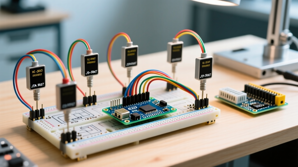
To ground the abstract question of what a sensor does in practical reality, let's look at the Analog Devices TMP36, a staple low-voltage analog temperature sensor. It outputs a linear voltage directly proportional to the Celsius temperature. Because it is an analog device, it requires a clean power supply and a direct connection to your microcontroller's ADC pin.
| Pin Number | Function | Specification / Range | Wiring Destination |
|---|---|---|---|
| 1 | VCC (Supply) | 2.7V to 5.5V DC | Microcontroller 5V or 3.3V pin |
| 2 | VOUT (Signal) | 0.1V to 2.0V Analog | Microcontroller ADC Pin (e.g., A0) |
| 3 | GND (Ground) | 0V Reference | Microcontroller GND |
The Math: Converting Raw ADC Reads to Physical Units
When an analog sensor sends a voltage to a microcontroller, the microcontroller doesn't see "19 degrees Celsius." It sees a raw integer generated by its internal ADC. To make the data useful, you must perform a two-step mathematical conversion: scaling the raw ADC integer back to a voltage, and then applying the sensor's specific transfer function to convert that voltage into a physical unit.
For a standard 5V Arduino Uno (ATmega328P), the ADC is 10-bit, meaning it maps the 0-5V range to integers between 0 and 1023. The Arduino analogRead reference confirms this resolution. The TMP36 outputs 10mV (0.01V) per degree Celsius, with a 500mV (0.5V) offset to allow for negative temperature readings.
Step 1: Raw ADC to Voltage
Voltage = (Raw_ADC_Value * 5.0) / 1024.0
Step 2: Voltage to Temperature (Celsius)
Temperature_C = (Voltage - 0.5) * 100.0
Here is the complete, copy-pasteable C++ code to implement this math, including a basic moving average to smooth out minor ADC jitter:
// TMP36 Analog Temperature Sensor Reading
// Target: Arduino Uno (5V logic, 10-bit ADC)

const int SENSOR_PIN = A0;
const float VCC_VOLTAGE = 5.0;
const int ADC_RESOLUTION = 1024;

void setup() {
  Serial.begin(115200);
  analogReference(DEFAULT); // Ensure 5V reference on Uno
}

void loop() {
  // Read raw ADC value
  int rawADC = analogRead(SENSOR_PIN);

  // Step 1: Convert raw ADC to Voltage
  float voltage = (rawADC * VCC_VOLTAGE) / ADC_RESOLUTION;

  // Step 2: Convert Voltage to Celsius (TMP36 transfer function)
  float tempC = (voltage - 0.5) * 100.0;

  // Convert to Fahrenheit for US users
  float tempF = (tempC * 9.0 / 5.0) + 32.0;

  Serial.print("Raw: "); Serial.print(rawADC);
  Serial.print(" | Voltage: "); Serial.print(voltage, 3);
  Serial.print("V | Temp: "); Serial.print(tempC, 1);
  Serial.print("C ("); Serial.print(tempF, 1); Serial.println("F)");

  delay(500);
}
Calibration and the ESP32 Caveat: The math above assumes a perfectly linear ADC. If you are using an ESP32 instead of an Arduino Uno, be aware that the ESP32's internal ADC is notoriously non-linear at the extremes (near 0V and 3.3V) and varies slightly from chip to chip. For precision analog sensing on an ESP32, bypass the internal ADC entirely and use an external 16-bit I2C ADC like the ADS1115. Furthermore, single-point offset calibration (adding or subtracting a fixed constant to match a known reference thermometer) is usually sufficient for the TMP36, but high-precision applications require a multi-point calibration curve stored in the microcontroller's EEPROM.
Frequently Asked Questions About Sensor Functions
What does a sensor do when it outputs a digital signal instead of analog?
When a sensor outputs a digital signal, it handles the analog-to-digital conversion and signal conditioning internally. Instead of outputting a variable voltage, it uses a digital communication protocol (like I2C, SPI, or 1-Wire) to transmit binary data packets. For example, a digital BME280 sensor measures temperature, pressure, and humidity, runs those raw analog readings through its internal calibration registers, and sends the final calculated physical values directly to your microcontroller. This eliminates the need for you to write raw-to-unit math in your code and drastically reduces susceptibility to cable noise, though it requires configuring specific library addresses and bus speeds.
What does a proximity sensor do differently than a mechanical limit switch?
A mechanical limit switch relies on physical contact to close an electrical circuit, meaning it suffers from mechanical wear, contact bounce, and physical degradation over time. A proximity sensor (whether inductive, capacitive, or optical) detects the presence of an object without physical contact. An inductive proximity sensor, for instance, generates a high-frequency electromagnetic field; when a metal object enters this field, it alters the oscillation amplitude, which the sensor's internal circuitry detects and translates into a clean, bounce-free digital HIGH or LOW signal. This makes proximity sensors vastly superior for high-cycle industrial environments where a mechanical switch would fail in weeks.
What does a sensor do if the wiring exceeds the maximum cable length?
If wiring exceeds the recommended length (typically 1 to 3 meters for unamplified analog sensors), the sensor's output signal degrades due to wire resistance, capacitance, and electromagnetic interference. The microcontroller will read a lower voltage than the sensor is actually outputting, and the signal will be heavily corrupted by noise. To fix this, you must either buffer the signal using an op-amp configured as a voltage follower at the sensor end, switch to a 4-20mA current loop (which is immune to voltage drop over long distances), or place a local microcontroller at the sensor to digitize the data and send it back via RS-485 or CAN bus.
Why does my sensor reading fluctuate, and what does a sensor do to filter noise?
Fluctuating readings are usually caused by power supply ripple, thermal noise, or EMI from nearby switching components (like relays or PWM-driven motors). Most basic analog sensors do not have internal filtering; they output the noise right along with the signal. To stabilize the reading, you must implement filtering. On the hardware side, add an RC low-pass filter (e.g., a 10kΩ resistor in series with the signal wire and a 0.1µF capacitor to ground) to smooth out high-frequency noise. On the software side, implement a moving average filter or an exponential smoothing algorithm in your code to discard transient spikes. For a deep dive into analog sensor noise rejection, Adafruit's thermistor and analog sensor guides offer excellent practical circuit examples.