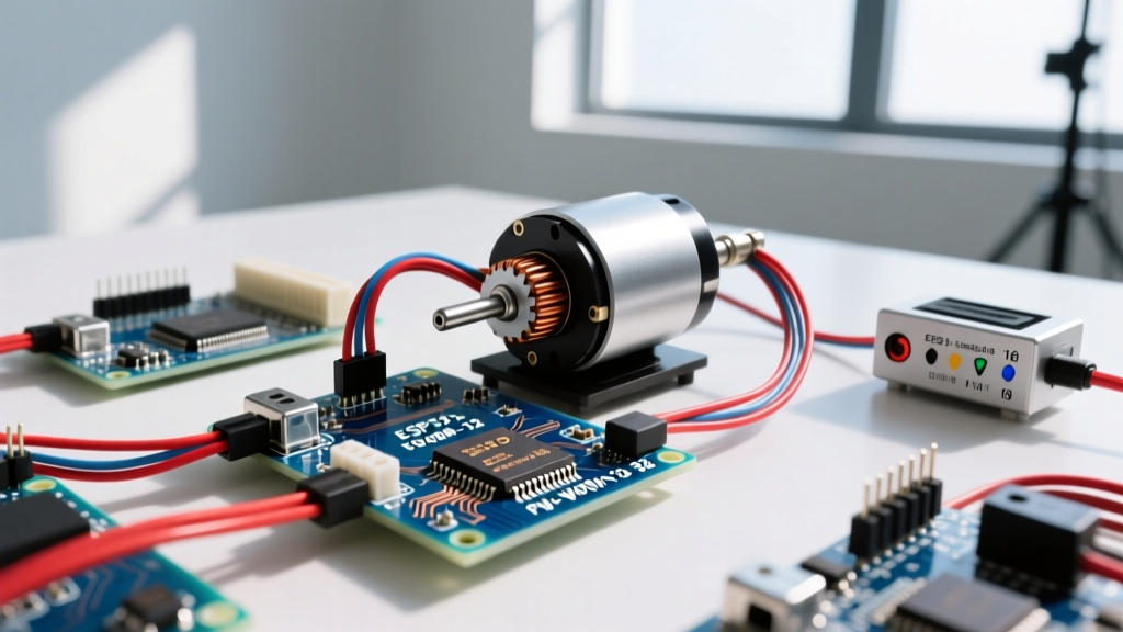

There is technically no such thing as a 'PWM motor.' Pulse Width Modulation (PWM) is a control method, not a motor topology. When hobbyists and embedded engineers search for a PWM motor, they are almost always looking for a brushed DC gearmotor paired with an H-bridge driver to achieve variable speed and direction control via a microcontroller. For 90% of embedded DIY projects requiring variable speed, a brushed DC gearmotor paired with a MOSFET-based driver (like the TB6612FNG or DRV8871) is the correct, most efficient default pick.
Selecting the right combination requires matching the mechanical load to the motor's torque curve, sizing the driver to handle stall current, and wiring the logic levels correctly. Here is the exact framework to size, wire, and debug your motor drive system.
The 'PWM Motor' Misconception: Matching Load to Motor Type
Before wiring up a driver, you must confirm that a PWM-controlled DC motor is actually what your load profile demands. Steppers and servos use entirely different control schemes (pulse trains and closed-loop feedback, respectively) and should never be treated as interchangeable with standard DC motors.
| Motor Type | Torque Curve | Control Needs | Cost & Complexity | Best PWM Application |
|---|---|---|---|---|
| Brushed DC | Max torque at stall, drops linearly as speed increases. | Simple H-bridge. PWM duty cycle controls speed; polarity controls direction. | Low ($5-$20). Simple 2-wire interface. | Wheeled robots, conveyors, winches, fans. |
| BLDC (Brushless) | High torque across a wide RPM band; highly efficient. | Requires 3-phase ESC (Electronic Speed Controller) or complex FOC driver. | Medium/High ($30-$100+). Needs 3-phase wiring. | Drones, high-speed propulsion, heavy continuous loads. |
| Stepper | High holding torque at zero speed; drops off sharply at high RPM. | Step/Dir pulses. Microstepping uses internal PWM, but speed is set by pulse frequency. | Medium ($15-$40). Requires 4+ wires and dedicated chopper driver. | CNC machines, 3D printers, precise linear actuators. |
Sizing Your PWM Motor: A Worked Load Example
The most common mistake in motor selection is sizing the driver for the motor's running current rather than its stall current. A DC motor draws maximum current when stalled (0 RPM) or starting from rest.
The Sizing Rule of Thumb:
1. Calculate continuous load current and add a 20% safety margin.
2. Select a motor whose continuous rating meets this number.
3. Select a driver whose peak current rating exceeds the motor's stall current (typically 5x to 8x the running current).
Worked Example: 3kg Differential Drive Robot
Imagine a 3kg robot chassis with 60mm diameter wheels (0.03m radius) navigating a slight incline.
- Force Required: ~10 Newtons to overcome rolling friction and a 10-degree incline.
- Torque per Motor: Force × Radius = 10N × 0.03m = 0.3 Nm (assuming two motors sharing the load, 0.15 Nm each, but we size for one motor taking the full load during a turn).
- Target Speed: 100 RPM (10.4 rad/s).
- Mechanical Power: Torque × Angular Velocity = 0.3 Nm × 10.4 rad/s = 3.12 Watts.
- Electrical Current (at 12V): Assuming 70% motor efficiency, Electrical Power = 3.12W / 0.70 = 4.45W. Continuous Current = 4.45W / 12V = 0.37A.
You need a motor rated for at least 0.45A continuous (0.37A + 20%). A standard 12V 775 gearmotor or a heavy-duty micro metal gearmotor fits this. If the motor's datasheet lists a stall current of 2.5A, your motor driver must be capable of handling at least 2.5A per channel without triggering thermal shutdown. For deep technical guidance on calculating DC motor parameters, refer to the Pololu Guide to DC Motors.
Driver Selection and Wiring: Terminals, Logic, and Power
Once you have a brushed DC motor, you need a driver to translate the microcontroller's 3.3V/5V PWM signals into high-current motor power. Forget the ancient L298N bipolar driver; it drops 2V to 3V across its internal transistors, wasting massive amounts of battery power as heat. Modern designs use MOSFET-based H-bridges.
| Driver IC | Continuous Current | Peak Current | Voltage Drop | Best For |
|---|---|---|---|---|
| TB6612FNG | 1.2A (per channel) | 3.2A | ~0.5V | Small robots, 6V-12V micro gearmotors. |
| DRV8871 | 3.6A | 6.0A | ~0.4V | Medium loads, 12V 775 motors, single-channel high torque. |
| BTS7960 | 20A+ | 43A | Very Low | Heavy machinery, e-bikes, massive 24V actuators. |
Wiring the TB6612FNG (Dual Channel)
The TB6612FNG is the gold standard for dual-microcontroller setups (like an ESP32 driving a two-wheel rover). Here is the exact terminal identification:
- VM: Motor power supply (e.g., 12V LiPo or bench supply). Keep this separate from logic power.
- VCC: Logic power (3.3V from ESP32 or 5V from Arduino). This powers the internal optocouplers/logic gates.
- GND: Common ground. Crucial: The motor power ground and microcontroller ground must be bonded together here.
- PWMA / PWMB: The PWM speed control pins. Connect to ESP32 LEDC pins or Arduino PWM pins.
- AIN1 / AIN2 (or BIN1/BIN2): Direction control. Set one HIGH and one LOW for forward; swap them for reverse; set both LOW to coast; set both HIGH to brake.
- STBY (Standby): Must be pulled HIGH (to VCC) to enable the chip. If left floating, the driver will not operate.
- AO1/AO2 & BO1/BO2: Motor output terminals. Polarity dictates direction.
analogWrite(), the ESP32 uses the LEDC (LED Control) peripheral for hardware PWM. You must use ledcAttach(pin, freq, resolution) and ledcWrite(pin, duty) in the Arduino IDE framework. Set the frequency to at least 1,000 Hz to avoid audible whining from the motor coils. Consult the Espressif LEDC API documentation for exact register configurations.
Failure Signatures: Diagnosing Hum, Overheat, and Stall
When a PWM motor circuit fails, the symptoms usually manifest acoustically or thermally before the silicon melts. Use this diagnostic path to identify the root cause.
- Audible Humming or Whining (No Movement):
Cause 1: PWM frequency is too low (e.g., 50Hz - 500Hz). The motor coils are physically vibrating at the switching frequency. Fix: Increase PWM frequency to 1kHz - 5kHz.
Cause 2: The motor is mechanically stalled, and the duty cycle is too low to overcome static friction (stiction). Fix: Implement a 'kickstart' routine in code—apply 100% duty cycle for 50ms, then drop to your target speed. - Driver Overheating (Too hot to touch within 30 seconds):
Cause 1: You are using an L298N driver at high currents. The bipolar junction transistors are dissipating watts as heat. Fix: Replace with a MOSFET driver (TB6612FNG or DRV8871).
Cause 2: The motor is partially stalled or binding, drawing continuous current near the stall rating. Fix: Check mechanical linkages for binding; verify gearmesh. - Motor Stalls Under Load but Runs Fine Unloaded:
Cause: Insufficient current delivery. The power supply is browning out, or the driver's peak current limit is triggering thermal/overcurrent protection. Fix: Measure the VM rail with a multimeter under load. If the 12V rail sags below 10V, your battery's C-rating or BEC is too low. Upgrade the power supply.
The Decision Path: Pick Your Exact Motor and Driver
Stop guessing. Use this decision matrix to select your exact hardware based on your mechanical load profile.
| Load Profile | Continuous Current | Stall/Peak Current | Recommended Motor | Recommended Driver |
|---|---|---|---|---|
| Light Rover / Pan-Tilt | < 0.5A | < 1.5A | Pololu Micro Metal Gearmotor (e.g., #4813) | TB6612FNG Breakout |
| Medium Robot / Conveyor | 0.5A - 2.0A | 2.0A - 5.0A | 12V 775 Brushed DC Gearmotor (100 RPM) | TI DRV8871 Breakout |
| Heavy Actuator / E-Bike | > 5.0A | > 15A | BaneBots RS-550 or 24V Windshield Wiper Motor | BTS7960 High-Power Module |
The Default Concrete Recommendation
If you are building a standard differential-drive robot or automated track system and need a reliable baseline to start coding today, buy this exact combination:
- The Motor: Two 12V 775 Brushed DC Gearmotors (rated ~100 RPM, 4A stall). They provide massive torque for their size, feature standard 5mm D-shafts, and mount easily to standard NEMA brackets.
- The Driver: Two DRV8871 Breakout Boards (one per motor). The DRV8871 handles up to 3.6A continuous and 6A peak, features integrated overcurrent protection, and requires only two microcontroller pins per motor (PWM for speed, GPIO for direction/braking via a simple logic inverter or dual-pin setup). Check the TI DRV8871 product page for the exact current derating curves based on your PCB copper weight.
- The Power: A 3S LiPo battery (11.1V nominal, 12.6V fully charged) with a minimum 40C discharge rating to handle the combined 8A stall current spike without voltage sag.
Wire the VM to the LiPo, bond the grounds, feed the ESP32's 3.3V to the DRV8871 VCC, and map your LEDC pins. You now have a robust, thermally stable PWM motor drive system ready for closed-loop encoder tuning.