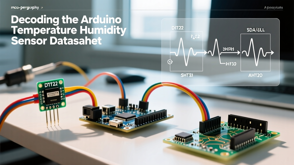

Beyond the Library: Why Datasheets Dictate Sensor Survival
Most tutorials covering an arduino temperature humidity sensor project stop at #include <DHT.h> and a basic wiring diagram. While this works for a weekend breadboard prototype, it inevitably fails in the field. Battery-powered weather stations drain in days, I2C buses lock up unpredictably, and sensors report 85% relative humidity (RH) while sitting in a dry room. These are not defective components; they are misunderstood datasheets.
To build robust environmental monitoring systems in 2026, you must bypass the abstraction of third-party libraries and read the silicon manufacturer's specifications. This guide dissects the datasheets of the three most common sensors on the market, translating microsecond timing diagrams, I2C command structures, and bus capacitance limits into actionable engineering data.
The 2026 Sensor Lineup: DHT22 vs. SHT31-D vs. AHT20
Before diving into protocol timings, we must establish the baseline specifications. The market has largely consolidated around three distinct architectures. Here is how they compare based on current 2026 datasheets and market pricing.
| Sensor Model | Protocol | Temp Accuracy | RH Accuracy | Avg Price (2026) | Sleep Current |
|---|---|---|---|---|---|
| Aosong DHT22 (AM2302) | Proprietary 1-Wire | ±0.5°C | ±2% RH | $3.50 | ~100 µA |
| Sensirion SHT31-D | I2C / SPI | ±0.2°C | ±2% RH | $6.50 | 0.2 µA |
| Aosong AHT20 | I2C | ±0.3°C | ±2% RH | $1.50 | ~20 µA |
DHT22 (AM2302): The Microsecond Minefield
The DHT22 uses a proprietary single-bus protocol. Unlike Dallas 1-Wire (DS18B20), the DHT22 protocol is entirely dependent on strict microsecond pulse-width timing. The Aosong DHT22 / AM2302 Datasheet hosted by SparkFun outlines a rigid handshake that leaves zero margin for operating system interrupts.
The Timing Handshake
- Start Signal: The Arduino host must pull the data line LOW for a minimum of 1ms (typically 1.5ms to ensure the sensor wakes), then release it HIGH for 20-40µs.
- Sensor Response: The DHT22 pulls the line LOW for 80µs, then HIGH for 80µs.
- Data Transmission: The sensor sends 40 bits (16-bit RH, 16-bit Temp, 8-bit checksum). A logic '0' is represented by 50µs LOW followed by 26-28µs HIGH. A logic '1' is 50µs LOW followed by 70µs HIGH.
Why delayMicroseconds() Fails on Modern MCUs
If you are running this on an ESP32 or an ATmega328P with active timer interrupts (like the millis() overflow or PWM generation), an interrupt firing during the 70µs HIGH pulse will stretch the timing. The Arduino Wire or DHT library will misinterpret a '1' as a '0', resulting in a checksum failure.
Actionable Fix: When writing bare-metal polling code for the DHT22, you must temporarily disable interrupts using noInterrupts() immediately after the start signal, and re-enable them with interrupts() only after the 40th bit is read. Alternatively, use hardware timer capture (Input Capture Unit on the ATmega328P) to measure pulse widths without blocking the CPU.
SHT31-D: Navigating I2C Commands and Clock Stretching
The Sensirion SHT31-D is the gold standard for professional environmental monitoring. However, its datasheet reveals a critical feature that frequently crashes standard Arduino I2C implementations: Clock Stretching.
Command Structures and Repeatability
The SHT31 does not simply spit out data when you read its I2C address. You must send specific command bytes to trigger a measurement. According to the Sensirion SHT31-DIS Digital Humidity Sensor Catalog, the sensor offers three repeatability modes:
0x2C 0x06: High repeatability (15ms measurement duration)0x2C 0x0D: Medium repeatability (6ms measurement duration)0x2C 0x10: Low repeatability (4ms measurement duration)
These commands utilize clock stretching. When the Arduino requests data immediately after sending the command, the SHT31 will hold the SCL (clock) line LOW until the measurement is complete. The hardware I2C peripheral on the ATmega328P handles this automatically, but software I2C libraries (like SoftwareWire) often lack robust timeout mechanisms for clock stretching, leading to infinite while-loops and a frozen microcontroller.
The Non-Stretching Alternative
To avoid bus lockups, use the non-stretching commands. Send 0x24 0x00 (High repeatability, no clock stretch). The sensor will immediately NACK if you try to read the data before 15ms has passed. You must implement a delay(15) or a non-blocking timer in your Arduino sketch between the write and read phases.
AHT20: The Hidden Calibration Command
The AHT20 is incredibly popular in 2026 due to its sub-$2 price point and I2C interface. Yet, forums are flooded with users reporting locked-up sensors or static readings of 0°C and 85% RH. The culprit is almost always a missed initialization sequence buried on page 7 of the Aosong datasheet.
The Mandatory Initialization Sequence
Unlike the SHT31, the AHT20 requires a specific calibration command upon every power-up before it can return valid data. If you skip this, the internal capacitive sensing matrix remains uncalibrated.
- Wait 40ms after VDD reaches 3.3V.
- Send the initialization command:
0xBE 0x08 0x00. - Wait 10ms.
- Read the status byte. Bit 3 (0x08) must be set to 1, indicating the sensor is calibrated. If it is 0, resend the
0xBEcommand.
Engineering Note: Many popular Arduino AHTX0 libraries fail to check the status byte after sending the init command. If the I2C bus is noisy and the 0xBE command is corrupted, the library proceeds to read uncalibrated garbage data. Always implement a status byte verification loop in your setup function.
Hardware Design: Calculating I2C Pull-Up Resistors
When wiring multiple I2C sensors (e.g., an SHT31 and a BME280) to an Arduino, the internal pull-up resistors (typically 20kΩ to 50kΩ on ATmega chips) are far too weak to pull the bus high within the required I2C rise-time specifications. You must add external pull-up resistors, but choosing the wrong value will cause communication failures.
The Pull-Up Math
According to the NXP I2C-bus specification and user manual (UM10204), the maximum allowed rise time for a 400kHz Fast-mode I2C bus is 300ns. The formula to calculate the maximum pull-up resistor value is:
Rp(max) = tr / (0.8473 * Cb)
Where tr is the rise time (300ns) and Cb is the total bus capacitance (traces, sensor pins, and Arduino pins).
- If your total bus capacitance is 150pF (typical for a small breadboard with two sensors):
Rp(max) = 300e-9 / (0.8473 * 150e-12) = 2,360 Ω
Actionable Advice: Use 2.2kΩ pull-up resistors to 3.3V for I2C sensor networks running at 400kHz. If you are running at 100kHz (Standard mode), the rise time limit is 1000ns, allowing you to safely use 4.7kΩ resistors, which reduces power consumption during the LOW state.
Thermal Mass and Self-Heating Errors
A frequently ignored section of temperature humidity sensor datasheets is the 'Self-Heating' specification. The internal ASIC and the measurement process generate heat. If the sensor is polled too frequently, or if it is enclosed in a poorly ventilated 3D-printed PETG enclosure, the reported temperature will be artificially high, which subsequently skews the RH calculation (since RH is temperature-dependent).
The SHT31 datasheet notes a self-heating effect of approximately 0.1°C at 3.3V in continuous measurement mode. The DHT22, lacking a low-power sleep state, runs warmer.
Mitigation Strategy: For battery-operated Arduino nodes, do not use continuous polling. Power the sensor via a GPIO pin (if the sensor draws less than 40mA, which all three of these do) or a MOSFET. Turn the VCC line on, wait for the sensor's startup time (e.g., 40ms for AHT20), take a single reading in high-repeatability mode, and immediately cut power. This eliminates self-heating errors and drops the average system current to the micro-amp range.
Summary of Best Practices
Successfully integrating an arduino temperature humidity sensor into a production or long-term deployment requires treating the component as a complex state machine rather than a simple analog probe. Respect the DHT22's microsecond timing by disabling interrupts, avoid I2C clock-stretching traps with the SHT31 by using delayed-read commands, and never skip the AHT20's calibration handshake. Finally, calculate your I2C pull-up resistors based on actual bus capacitance to ensure clean signal edges. By adhering strictly to the datasheet parameters, your environmental monitoring projects will achieve the accuracy and reliability required for professional 2026 applications.