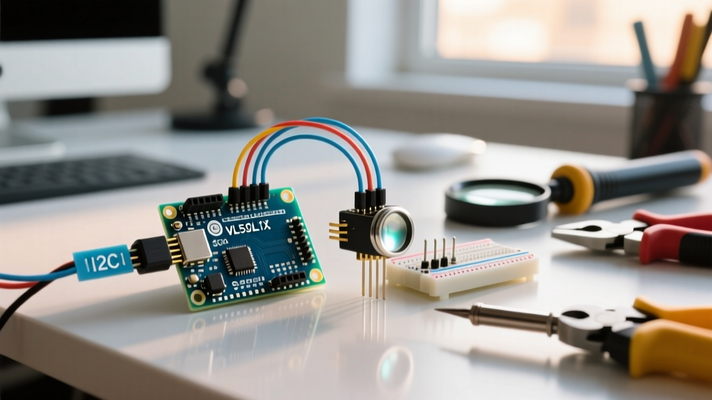
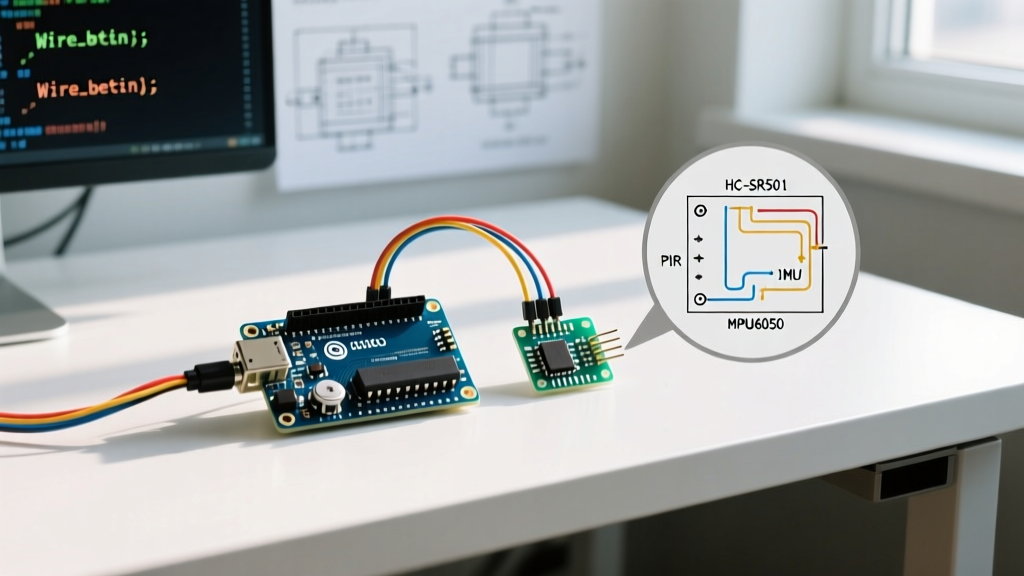
If you've landed here searching for a 'sensor sensor Arduino' guide, you're likely trying to daisy-chain multiple environmental or motion sensors onto a single microcontroller without running out of pins. When you move past single-sensor blink-and-read projects, the physical and electrical realities of the I2C bus come into play. The direct answer to connecting multiple sensors to an Arduino is to utilize the I2C (Inter-Integrated Circuit) protocol on pins A4 (SDA) and A5 (SCL), allowing you to chain up to 128 devices provided their hex addresses do not clash.
Difficulty: Intermediate
Time to Complete: 45 Minutes
Target Board Variant: Arduino Uno R3 (ATmega328P)
Operating Voltage: 5V Logic (with 3.3V sensor regulation)
Parts List & Hardware Specifications
To demonstrate a robust multi-sensor bus, we are pairing an environmental sensor with a 6-axis motion tracker. Both use I2C, but they have different logic-level tolerances and default addresses. As of 2026, generic breakout boards are cheaper but often lack onboard voltage regulation, making the branded variants worth the extra few dollars for reliable I2C pull-ups.
| Component | Exact Variant / Model | Approx. Price | Engineering Notes |
|---|---|---|---|
| Microcontroller | Arduino Uno R3 (ATmega328P) | $27.00 | 5V logic, 16MHz clock. A4=SDA, A5=SCL. |
| Env. Sensor | Adafruit BME280 (PID 2652) | $14.95 | Includes onboard 3.3V regulator and I2C pull-ups. Default I2C: 0x77 (or 0x76). |
| Motion Sensor | MPU6050 (GY-521 Breakout) | $3.50 | Generic board. Has 3.3V LDO but weak pull-ups. Default I2C: 0x68. |
| Wiring | 24 AWG Solid Core Jumper Wires | $5.00 | Keep I2C traces under 30cm to avoid capacitance issues. |
| Resistors | 4.7kΩ Pull-up Resistors (x2) | $0.10 | Required if using multiple generic sensors without onboard pull-ups. |
Pin Mapping & Wiring Procedure
The most common point of failure in multi-sensor Arduino builds is logic-level mismatch. The Arduino Uno R3 operates at 5V, but the BME280 and MPU6050 silicon are strictly 3.3V. While the Adafruit BME280 breakout protects you with an onboard regulator and level shifters, the generic GY-521 MPU6050 board relies on a cheap LDO that can overheat if fed 5V on the VCC pin for extended periods.
Pin Mapping Table
| Sensor Pin | Arduino Uno R3 Pin | Wire Color (Suggested) |
|---|---|---|
| BME280 VIN | 5V | Red |
| BME280 GND | GND | Black |
| BME280 SCK (SCL) | A5 | Blue |
| BME280 SDI (SDA) | A4 | Yellow |
| MPU6050 VCC | 3.3V | Orange |
| MPU6050 GND | GND | Black |
| MPU6050 SCL | A5 | Blue (tied to BME SCL) |
| MPU6050 SDA | A4 | Yellow (tied to BME SDA) |
- Power the Rails: Connect the Arduino 5V and GND to the left breadboard rails. Connect the Arduino 3.3V to the right breadboard rail.
- Wire the BME280: Connect VIN to 5V, GND to GND, SCL to A5, and SDA to A4. Because this is an Adafruit board, it safely steps down the 5V I2C logic to 3.3V.
- Wire the MPU6050: Connect VCC strictly to the 3.3V rail. Connect GND to GND. Tie SCL and SDA to the same A5 and A4 nodes used by the BME280.
- Verify Pull-ups: The Adafruit BME280 has 10kΩ pull-ups enabled by default. This is sufficient for a short bus with one additional sensor. If you add a third generic sensor, solder 4.7kΩ resistors between the SDA/SCL lines and the 3.3V rail to ensure clean square waves.
Complete C++ Code with Error Handling
This code targets the Arduino Uno R3 (ATmega328P). It utilizes the Adafruit unified sensor libraries. Before uploading, ensure you have installed the Adafruit BME280 Library and Adafruit MPU6050 Library via the Arduino Library Manager.
#include <Wire.h>
#include <Adafruit_Sensor.h>
#include <Adafruit_BME280.h>
#include <Adafruit_MPU6050.h>

// Pin definitions (Hardware I2C on Uno R3)
#define I2C_SDA A4
#define I2C_SCL A5

// Sensor objects
Adafruit_BME280 bme;
Adafruit_MPU6050 mpu;

// Sea level pressure for altitude calculation
#define SEALEVELHPA (1013.25)

void setup() {
  Serial.begin(115200);
  while (!Serial) delay(10); // Wait for serial port to connect

  Serial.println(F("Multi-Sensor I2C Bus Initialization..."));

  // Initialize I2C bus
  Wire.begin(I2C_SDA, I2C_SCL);
  Wire.setClock(400000); // Set I2C clock to 400kHz (Fast Mode)

  // Initialize BME280 (Default address 0x77, some clones use 0x76)
  if (!bme.begin(0x77)) {
    Serial.println(F("ERROR: Could not find a valid BME280 sensor, check wiring, address, sensor ID!"));
    // Halt execution to prevent reading garbage data
    while (1) { delay(10); }
  }
  Serial.println(F("BME280 Initialized Successfully."));

  // Initialize MPU6050 (Default address 0x68)
  if (!mpu.begin(0x68)) {
    Serial.println(F("ERROR: Failed to find MPU6050 chip at 0x68!"));
    while (1) { delay(10); }
  }
  Serial.println(F("MPU6050 Initialized Successfully."));

  // Configure MPU6050 ranges
  mpu.setAccelerometerRange(MPU6050_RANGE_8_G);
  mpu.setGyroRange(MPU6050_RANGE_500_DEG);
  mpu.setFilterBandwidth(MPU6050_BAND_21_HZ);

  Serial.println(F("--- All Sensors Online ---"));
  delay(100);
}

void loop() {
  // Read BME280
  float temp = bme.readTemperature();
  float humidity = bme.readHumidity();

  // Read MPU6050
  sensors_event_t a, g, temp_mpu;
  mpu.getEvent(&a, &g, &temp_mpu);

  // Print formatted data
  Serial.print("Temp: "); Serial.print(temp); Serial.print(" *C | ");
  Serial.print("Hum: "); Serial.print(humidity); Serial.print(" % | ");
  Serial.print("Accel X: "); Serial.print(a.acceleration.x); Serial.println(" m/s^2");

  delay(500); // 2Hz read rate
}
Debugging: First Three Checks & Common Error Strings
When an I2C bus fails, it usually fails silently or throws a specific initialization error. If your serial monitor halts, here is how to diagnose it.
1. Run an I2C Scanner: Upload a basic I2C scanner sketch. If the scanner returns no addresses, your SDA/SCL wires are swapped, or you are missing a common ground.
2. Verify Logic Levels: Measure the voltage on the SDA and SCL lines with a multimeter. They should idle near 3.3V (or 5V if using 5V pull-ups). If they read 0V, a sensor is shorting the bus to ground.
3. Check Address Clashes: Ensure no two sensors share the same hex address. If you have two BME280s, one must have its SDO pin tied to VCC to shift its address to 0x76.
Exact Error String: "Could not find a valid BME280 sensor, check wiring, address, sensor ID!"
This is the exact error string thrown by the Adafruit BME280 library when the bme.begin() function fails. Here are the ranked causes:
- Wrong I2C Address (Most Likely): You passed
0x77to the code, but your specific breakout board defaults to0x76. Check the silkscreen on the board or run an I2C scanner to find the actual address. - Missing Power / Blown LDO: If you fed 5V into the raw 3.3V pin of a generic BME280, you have likely destroyed the onboard voltage regulator. The chip will not respond to I2C polling.
- Capacitance Overload: If your wires are longer than 30cm, the bus capacitance exceeds the 400pF I2C spec, rounding off the square waves into triangles. The Arduino misses the ACK bit. Lower the clock speed in code using
Wire.setClock(100000);.
Exact Error String: "SensorID was 0xFF"
Sometimes the library finds an I2C device at the correct address, but throws this secondary error. This means the Arduino successfully pinged the address, but when it read the WHO_AM_I register, it received 0xFF. This almost always indicates a corrupted chip, a counterfeit sensor silicon die, or that a completely different sensor is sitting at that address and returning garbage data when queried for a BME280 ID.
Extending and Simplifying Your Sensor Build
Once you master the basic two-sensor bus, you will inevitably want to add more. Here is how to scale your architecture.
How to Extend: The I2C Multiplexer
If you need to connect three identical sensors (e.g., three BME280s for multi-room temperature tracking), you will hit an address wall. The solution is the TCA9548A I2C Multiplexer (approx. $6). This chip sits on the main I2C bus and creates 8 independent sub-buses. You send a command to the multiplexer to open 'Channel 1', read the sensor, then switch to 'Channel 2' and read the next. This completely isolates capacitance and prevents address clashes.
How to Simplify: Upgrade the Microcontroller
If your end goal is to log this sensor data to the cloud, the Arduino Uno R3 requires a bulky external WiFi shield or ESP-01 module wired via UART. To simplify the physical build, migrate your code to an ESP32 DevKit V1. The ESP32 features native WiFi, dual-core processing, and two hardware I2C buses, allowing you to separate noisy motion sensors from sensitive environmental sensors natively without a multiplexer.
Frequently Asked Questions
Can I connect two identical sensors to the same Arduino I2C bus?
Only if the sensor breakout board includes a physical jumper or pad to change its I2C address. For example, the MPU6050 has an AD0 pin; pulling it high changes the address from 0x68 to 0x69. If your sensor lacks an address-selection pin, you must use a TCA9548A I2C multiplexer to run them on separate logical buses.
Why does my Arduino sensor reading drift after a few hours?
Thermal drift is common when sensors are placed too close to the microcontroller. The Arduino's voltage regulator and ATmega328P chip generate heat. If your BME280 is mounted directly above the Arduino's USB port or voltage regulator, it will read temperatures 2°C to 4°C higher than ambient. Always mount environmental sensors on a short extension cable away from the main board's heat envelope.
What is the maximum wire length for an Arduino I2C sensor bus?
The I2C specification was designed for on-board communication, not long-distance runs. At 400kHz (Fast Mode), reliable bus length is generally limited to 30 centimeters (12 inches). If you must run I2C sensors over longer distances (up to 2 meters), drop the bus speed to 100kHz using Wire.setClock(100000);, use twisted-pair cable, and ensure strong 2.2kΩ pull-up resistors are installed at the master end.
How do I resolve an I2C address conflict between two sensors?
First, consult the datasheets for both sensors to see if either supports address shifting via a hardware pin (like SDO or AD0). If neither supports address changing, and you cannot use a multiplexer, your final option is software I2C (bit-banging). Use the SoftwareWire library to create a secondary, virtual I2C bus on two digital pins (e.g., D2 and D3), isolating the conflicting sensor from the main hardware bus.