To connect an LCD screen to an Arduino, the most reliable and breadboard-friendly method is using a 16x2 HD44780-compatible display equipped with an I2C backpack (typically based on the PCF8574 or PCF8574A chip). This reduces the required wiring from 16 parallel pins down to just 4 (VCC, GND, SDA, SCL), freeing up your microcontroller's GPIO pins for actual sensors and actuators.
This guide targets the Arduino Uno R3 (ATmega328P, 5V logic) and walks through the exact wiring, provides production-ready code with pre-flight I2C error handling, and details the specific debugging steps for the most common hardware and software failures.
Parts List & Specification Sheet
Before you start stripping wires, verify your exact hardware variants. The I2C address of your LCD depends entirely on which expander chip is soldered to the backpack.
| Component | Exact Variant / Model | Specifications & Notes |
|---|---|---|
| Microcontroller | Arduino Uno R3 (or R4 Minima) | 5V logic, 16MHz. SDA on A4, SCL on A5. |
| LCD Module | 16x2 HD44780 with I2C Backpack | Look for the 4-pin header. Ensure it has a blue contrast trimpot. |
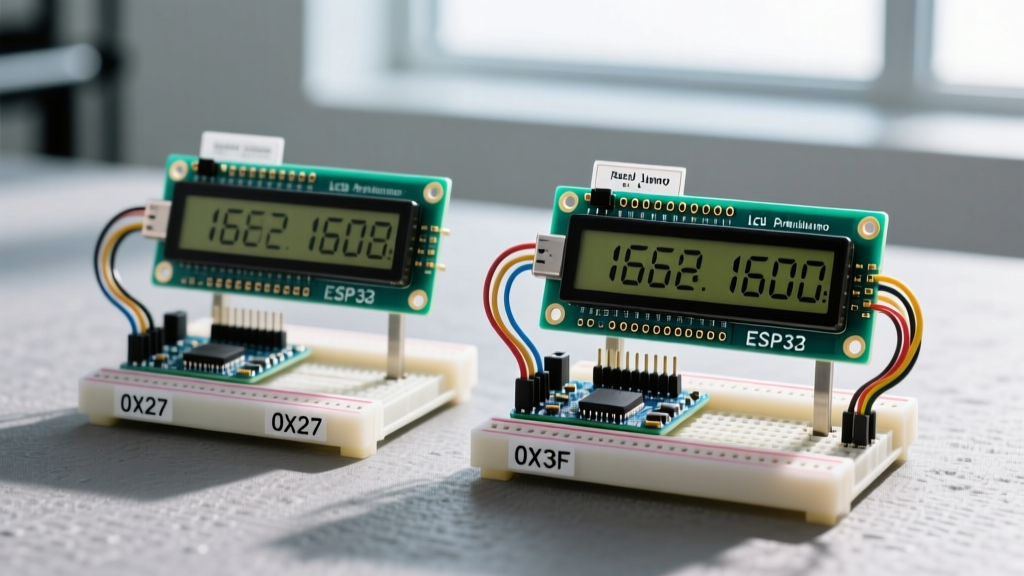
| I2C Expander Chip | PCF8574 OR PCF8574A | PCF8574: Base address 0x20 (usually 0x27). PCF8574A: Base address 0x38 (usually 0x3F). |
| Wiring | 22 AWG Solid Core Jumper Wires | 4 wires required. Keep I2C runs under 1 meter to avoid capacitance issues. |
Pin Mapping & Wiring Steps
The I2C protocol uses an open-drain architecture, meaning it relies on pull-up resistors to pull the line high. Fortunately, almost all commercial I2C LCD backpacks include 4.7kΩ pull-up resistors on the SDA and SCL lines. You do not need to add external resistors for a single LCD on a short bus.
| LCD Backpack Pin | Arduino Uno R3 Pin | Function |
|---|---|---|
| GND | GND | Common ground reference. |
| VCC | 5V | Power supply (requires ~20mA with backlight on). |
| SDA | A4 | Serial Data Line (bidirectional). |
| SCL | A5 | Serial Clock Line (driven by Arduino). |
Numbered Wiring Steps
- De-energize the board: Unplug the Arduino from USB before making I2C connections to prevent accidental shorting of the 5V rail to the SDA line.
- Connect Power: Route the GND and 5V pins from the Arduino to the LCD backpack.
- Connect Data: Connect A4 to SDA and A5 to SCL. If you are using an Arduino Mega 2560 instead of an Uno, SDA is pin 20 and SCL is pin 21.
- Verify the Trimpot: Look at the blue potentiometer on the back of the I2C backpack. Turn it fully counter-clockwise to start with minimum contrast.
- Power Up: Plug the Arduino into your PC via USB. The LCD backlight should illuminate immediately.
Complete Compilable Code (Arduino Uno R3)
This code targets the Arduino Uno R3. It uses the standard Wire library to ping the I2C address before attempting to initialize the display. This prevents the silent failures common in basic tutorials where a wrong address results in a frozen setup() loop.
Prerequisite: Install the LiquidCrystal I2C library by Frank de Brabander via the Arduino Library Manager.
#include <Wire.h>
#include <LiquidCrystal_I2C.h>

// Define the I2C address, columns, and rows
// Most PCF8574 backpacks are 0x27, PCF8574A are 0x3F
#define LCD_ADDRESS 0x27
#define LCD_COLUMNS 16
#define LCD_ROWS 2

LiquidCrystal_I2C lcd(LCD_ADDRESS, LCD_COLUMNS, LCD_ROWS);

void setup() {
  Serial.begin(115200);
  Wire.begin();

  // ERROR HANDLING: Ping the I2C address before initializing
  Wire.beginTransmission(LCD_ADDRESS);
  byte error = Wire.endTransmission();

  if (error == 0) {
    Serial.println("I2C LCD found. Initializing...");
    lcd.init();
    lcd.backlight();
    lcd.setCursor(0, 0);
    lcd.print("ElectricalFlux");
    lcd.setCursor(0, 1);
    lcd.print("LCD Ready!");
  } else if (error == 2) {
    // Exact error string for address mismatch or disconnected SDA
    Serial.println("ERROR: I2C device not found at address 0x27. Check wiring or try 0x3F.");
    while(1) { delay(1000); } // Halt execution
  } else if (error == 4) {
    Serial.println("ERROR: I2C unknown error at address. Check for SDA/SCL short.");
    while(1) { delay(1000); }
  } else {
    Serial.print("I2C Error code: ");
    Serial.println(error);
    while(1) { delay(1000); }
  }
}

void loop() {
  // Main application logic goes here
  delay(1000);
}
Debugging: First 3 Things to Check When It Fails
When your LCD screen Arduino setup fails to display text, do not immediately rewrite your code. Hardware and protocol mismatches cause 95% of these failures. Here are the first three things to check, ranked by probability.
1. The I2C Address Mismatch (0x27 vs 0x3F)
Symptom: The backlight turns on, but the screen is blank. The serial monitor outputs: "ERROR: I2C device not found at address 0x27. Check wiring or try 0x3F."
Ranked Causes:
- Wrong Expander Chip: Your board uses a PCF8574A (address 0x3F) instead of a PCF8574 (address 0x27). Change
#define LCD_ADDRESS 0x27to0x3Fin the code. - Address Jumpers: Some backpacks have A0, A1, and A2 solder pads. If these are bridged, the address shifts. Use an I2C Scanner sketch to find the exact hex address.
- SDA/SCL Swapped: Reversing these pins won't fry the board, but the I2C bus will fail to acknowledge. Verify A4 is SDA and A5 is SCL.
2. The Contrast Voltage Divider (Black Boxes)
Symptom: The top row displays solid black squares, and the bottom row is blank. The serial monitor shows successful initialization.
The Fix: This is purely an analog voltage issue. The HD44780 controller requires the V0 (contrast) pin to be roughly 0.5V to 1.0V below VCC. The blue trimpot on the backpack acts as a voltage divider. Take a small Phillips screwdriver and slowly turn the trimpot clockwise until the black squares fade into readable text. If the trimpot is stripped or broken, you can bypass it by wiring a 1kΩ resistor between the V0 pad and GND.
3. Logic Level Mismatch (5V vs 3.3V)
Symptom: Gibberish characters, intermittent freezing, or the ESP32/Teensy browning out.
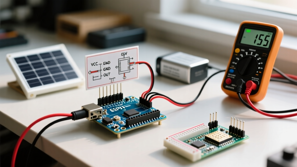
The Fix: Standard I2C LCD backpacks are designed for 5V logic (like the Arduino Uno). If you connect one directly to a 3.3V board (like an ESP32 or Raspberry Pi Pico), the 5V pull-up resistors on the backpack will feed 5V back into the 3.3V GPIO pins. This exceeds the absolute maximum ratings and causes let-through current that degrades the silicon over time. You must use a bidirectional logic level shifter (like the BSS138-based Adafruit 4-channel shifter) between the 3.3V microcontroller and the 5V LCD.
Extending and Simplifying the Build
Once you have the baseline 16x2 display working, you can easily scale the project up or down without rewriting your core logic.
How to Simplify: Upgrade to 20x4
If you need more screen real estate, swap the 16x2 glass for a 20x4 HD44780 module. The I2C backpack pinout and wiring remain identical. In your code, simply update the definitions:
#define LCD_COLUMNS 20
#define LCD_ROWS 4
The LiquidCrystal_I2C library handles the internal memory mapping differences automatically. Note that on 20x4 displays, the physical row order in memory is 1, 3, 2, 4, but the library abstracts this so lcd.setCursor(0, 3) still correctly targets the bottom row.
How to Extend: Multiple LCDs on One Bus
Because I2C is a bus protocol, you can wire up to eight LCD screens to a single Arduino Uno. To do this, you must change the I2C addresses so they don't collide. Look for the A0, A1, and A2 pads on the back of the PCF8574 backpack. By cutting the default traces and soldering jumper pads, you can shift the base address. Refer to the Adafruit I2C Address Guide for the exact binary-to-hex mapping table for the PCF8574.
Frequently Asked Questions
How do I find the I2C address for my LCD screen Arduino setup?
If the default 0x27 or 0x3F addresses fail, upload a standard 'I2C Scanner' sketch (available via File > Examples > Wire > I2CScanner in newer IDE versions, or from the Arduino Playground). Open the Serial Monitor at 115200 baud. The scanner will sweep the bus and print the exact hexadecimal address of any responding device. If it returns 'No I2C devices found', you have a wiring fault or a dead pull-up resistor on the backpack.
Why is my LCD screen Arduino showing black boxes on the top row?
Solid black boxes on the first row indicate that the LCD controller has successfully powered on and initialized its internal RAM, but the contrast voltage (V0) is set too high. The liquid crystals are fully twisted, blocking all light. Adjust the blue potentiometer on the I2C backpack counter-clockwise until the text becomes visible. If the potentiometer has no effect, the wiper pin may be disconnected from the circuit; verify your solder joints on the 16-pin header connecting the backpack to the glass.
Can I use a 5V LCD screen with an Arduino ESP32 without frying it?
Not directly. The ESP32 operates at 3.3V logic, while standard I2C LCD backpacks use 5V and include 4.7kΩ pull-up resistors tied to the 5V rail. Connecting them directly will force 5V into the ESP32's SDA and SCL pins, which can permanently damage the GPIO matrix over time due to let-through current. You must either power the LCD backpack with 3.3V (which may result in a dim backlight and require removing the 5V pull-ups) or use a dedicated bidirectional logic level shifter to safely bridge the 3.3V and 5V domains.