
The ESP32 OLED Display Black Screen Dilemma
Integrating an ESP32 OLED display into your microcontroller project is a rite of passage for DIY electronics enthusiasts. Whether you are building a custom smart home thermostat, a portable weather station, or a real-time telemetry dashboard, the ubiquitous 0.96-inch 128x64 I2C OLED module is the go-to choice. However, the journey from breadboard to functional interface is frequently interrupted by the dreaded black screen of death. When your ESP32 OLED display refuses to initialize, the root cause is rarely a defective screen. Instead, it is almost always a subtle mismatch in I2C addressing, logic level thresholds, or memory buffer allocation. This comprehensive troubleshooting guide bypasses basic tutorials and dives deep into the electrical and software realities of interfacing OLED peripherals with the ESP32 ecosystem.
I2C Bus Address Conflicts and Pin Mapping
The I2C protocol relies on strict hardware addressing. Most 0.96-inch SSD1306 modules default to the 7-bit I2C address of 0x3C. However, some manufacturers configure the address resistor to pull the line high, resulting in an address of 0x3D. If your Arduino or ESP-IDF code initializes the display at 0x3C but the hardware expects 0x3D, the initialization handshake will silently fail. To resolve this, upload a standard I2C Scanner sketch to your ESP32. This utility sweeps the I2C bus and prints the addresses of all responding devices to the serial monitor. According to the Random Nerd Tutorials ESP32 I2C guide, ensuring your software address matches the hardware reality is the most critical first step in peripheral debugging.
ESP32 DevKit vs. ESP32-S3 Pinout Differences
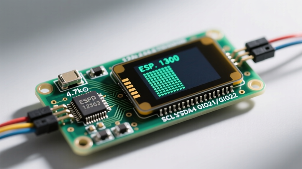
Hardware pin mapping is another frequent point of failure. The original ESP32 DevKit V1 defaults to GPIO 21 for SDA and GPIO 22 for SCL. If you are using the standard Wire library without explicitly defining pins, the Arduino core assumes these defaults. However, the ESP32 ecosystem has expanded dramatically. If you are using an ESP32-S3, ESP32-C3, or a specialized board like the LilyGo T-Display, the default I2C pins are entirely different. For instance, the ESP32-S3 does not have hardcoded default I2C pins in many Arduino core versions. You must explicitly declare your pins using Wire.begin(SDA_PIN, SCL_PIN). Failing to do so will result in the ESP32 attempting to toggle non-existent or incorrect GPIOs, leaving your ESP32 OLED display completely unresponsive.
Resolving Logic Level and Pull-Up Resistor Failures
The ESP32 is strictly a 3.3V logic device. Its GPIO pins are not 5V tolerant, and applying 5V to an ESP32 input will permanently damage the silicon. Many hobbyists power their OLED modules using the 5V pin on the ESP32 dev board, assuming the OLED requires 5V. While the OLED's internal charge pump can handle a 5V VCC input, this creates a dangerous logic level mismatch on the I2C bus. If the OLED module has onboard pull-up resistors tied to its 5V VCC rail, the SDA and SCL lines will be pulled up to 5V. When the ESP32 attempts to read the bus, it will be subjected to 5V, risking hardware destruction. Furthermore, when the ESP32 outputs a 3.3V HIGH signal, the OLED's I2C controller might not recognize it as a valid logic HIGH if its Vih threshold is calibrated for 5V operation. The definitive solution is to power the OLED module from the ESP32's 3.3V pin. If your specific OLED module requires 5V for adequate brightness, you must use a bidirectional logic level shifter (such as the BSS138 MOSFET-based shifters) on the SDA and SCL lines, and ensure external 4.7kΩ pull-up resistors are tied to the 3.3V rail on the ESP32 side.
Software Stack: U8g2 vs. Adafruit_SSD1306 Library Clashes
Once the hardware is verified, software library conflicts frequently cause initialization crashes or memory allocation failures. The Adafruit SSD1306 library is the most popular choice for beginners, but it requires a contiguous 1024-byte RAM buffer for a 128x64 display (128 * 64 / 8 bits). On an ESP32 running complex tasks like Wi-Fi provisioning or Bluetooth LE scanning, the heap can become fragmented. If the Adafruit library cannot find a contiguous 1KB block during the display.begin() call, it will fail silently or trigger a Guru Meditation Error (heap allocation failure). To bypass this, professional firmware developers prefer the U8g2 library. U8g2 supports page-buffering, which reduces the RAM footprint to a fraction of the full-screen buffer by rendering the display in horizontal slices. When migrating to U8g2, ensure you select the correct constructor for your specific I2C address and rotation.
Correcting the I2C Clock Speed Bottleneck
I2C is a relatively slow protocol, and signal integrity degrades rapidly with poor wiring. The default I2C clock speed on the ESP32 is often set to 400kHz (Fast Mode). If you are using long jumper wires or a breadboard with high parasitic capacitance, the 400kHz square waves will degrade into triangular ramps, causing the OLED controller to misinterpret the data bits. According to the Espressif ESP-IDF I2C documentation, you can manually throttle the I2C clock speed to improve reliability. By adding Wire.setClock(100000); before initializing the display, you force the bus into Standard Mode (100kHz), giving the RC circuit formed by your wires and pull-up resistors enough time to reach a valid logic HIGH threshold.
Hardware Diagnostic Matrix for SSD1306 and SH1106 Modules
| Symptom | Probable Cause | Diagnostic Action | Resolution |
|---|---|---|---|
| Screen is completely black | VCC/GND swapped or I2C address mismatch | Run I2C Scanner sketch; check continuity | Correct wiring; update address to 0x3C or 0x3D |
| Display shows static noise/snow | SH1106 driven by SSD1306 library | Check module datasheet | Switch to SH1106 driver or U8g2 SH1106 constructor |
| Image is shifted 4 pixels right | SH1106 RAM offset error | Observe alignment of test pattern | Use SH1106-specific library which handles 132x64 internal RAM |
| ESP32 reboots randomly | Heap allocation failure or 5V backfeed | Monitor serial output for Guru Meditation | Use U8g2 page buffer; add logic level shifter |
| Flickering or tearing artifacts | I2C bus capacitance too high | Measure wire length; check pull-ups | Lower clock to 100kHz; add 4.7kΩ pull-ups to 3.3V |
Advanced Scope Tracing and Signal Integrity
When multimeter continuity checks and software tweaks fail, you must move to oscilloscope diagnostics. Connect your scope probes to the SDA and SCL lines at the OLED module header. A healthy I2C signal should exhibit sharp, square falling edges (driven by the open-drain MOSFETs pulling to ground) and slightly rounded rising edges (determined by the RC time constant of the pull-up resistors and bus capacitance). If the rising edge takes longer than 300 nanoseconds to cross the 2.0V threshold, the OLED controller will drop bits. To fix this, you must either decrease the pull-up resistor value to 2.2kΩ to source more current and charge the parasitic capacitance faster, or physically shorten the I2C traces. Never route I2C lines parallel to high-current PWM motor traces or SPI clock lines, as capacitive crosstalk will inject false clock pulses into the OLED display controller, resulting in corrupted frame buffers and permanent screen lockups until a hard power cycle is performed.