
The Hardware Reality: XIAO ESP32S3 Sense Architecture
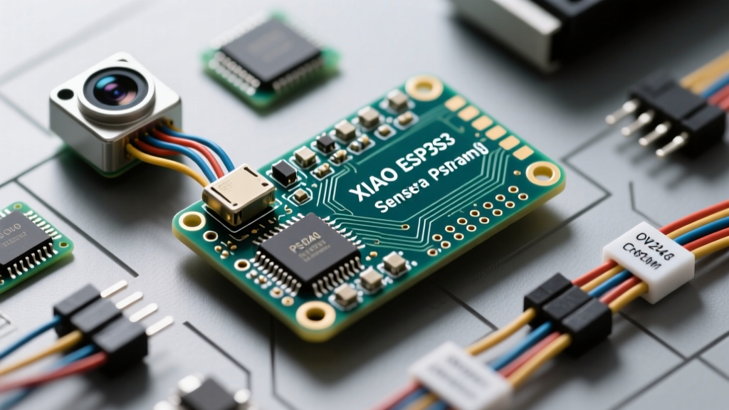
The Seeed Studio XIAO ESP32S3 Sense represents a massive leap in edge-computing miniaturization. Measuring just 21 x 17.5mm, it integrates an ESP32-S3R8 SoC (dual-core Xtensa LX7 at 240MHz), 16MB of Flash, 8MB of OPI PSRAM, an OV2640 camera module, and an MSM261D3526H1CPM digital microphone. However, configuring this board in the Arduino IDE requires navigating specific Espressif core quirks, managing strict memory bus allocations, and mitigating hardware power delivery limitations.
This configuration guide bypasses generic tutorials and dives directly into the exact pin mappings, PSRAM allocation strategies, and power failure modes you will encounter when deploying the XIAO ESP32S3 Sense in production or advanced DIY environments.
Arduino IDE 2.x Board Manager Configuration
Before writing a single line of code, your Arduino IDE environment must be configured to recognize the specific memory layout of the S3R8 chip. The standard ESP32 core often defaults to QSPI PSRAM, which will cause immediate initialization failures on this specific board.
- Open Board Manager and search for
esp32by Espressif Systems. Version 2.0.14 is currently the most stable for camera implementations, though v3.0.x offers better FreeRTOS integration. For camera stability, stick to 2.0.14 unless you require the latest ESP-IDF v5.1 features. - Select Tools > Board > esp32 > XIAO_ESP32S3.
- Critical Step: Navigate to Tools > PSRAM and select OPI PSRAM. The XIAO Sense utilizes Octal Peripheral Interface (OPI) RAM. If left on 'Disabled' or 'QSPI', the camera framebuffer allocation will fail silently or throw a
0x20001error. - Set Flash Size to 16MB (128Mb) and Partition Scheme to Huge APP (3MB No OTA/1MB SPIFFS) to accommodate heavy TensorFlow Lite models alongside your sketch.
OV2640 Camera Pin Mapping & Initialization
Unlike larger ESP32-CAM boards that use standard GPIO headers, the XIAO ESP32S3 Sense routes the OV2640 camera through a high-density B2B (board-to-board) connector. The pin mappings are hardcoded to the SoC's native camera interface. According to the Seeed Studio XIAO ESP32S3 Wiki, the exact pinout for the camera_config_t struct is as follows:
#include "esp_camera.h"

#define PWDN_GPIO_NUM     -1
#define RESET_GPIO_NUM    21
#define XCLK_GPIO_NUM     10
#define SIOD_GPIO_NUM     40
#define SIOC_GPIO_NUM     39

#define Y9_GPIO_NUM       48
#define Y8_GPIO_NUM       11
#define Y7_GPIO_NUM       12
#define Y6_GPIO_NUM       14
#define Y5_GPIO_NUM       16
#define Y4_GPIO_NUM       18
#define Y3_GPIO_NUM       17
#define Y2_GPIO_NUM       15
#define VSYNC_GPIO_NUM    38
#define HREF_GPIO_NUM     47
#define PCLK_GPIO_NUM     13

void initCamera() {
  camera_config_t config;
  config.ledc_channel = LEDC_CHANNEL_0;
  config.ledc_timer = LEDC_TIMER_0;
  config.pin_d0 = Y2_GPIO_NUM;
  config.pin_d1 = Y3_GPIO_NUM;
  config.pin_d2 = Y4_GPIO_NUM;
  config.pin_d3 = Y5_GPIO_NUM;
  config.pin_d4 = Y6_GPIO_NUM;
  config.pin_d5 = Y7_GPIO_NUM;
  config.pin_d6 = Y8_GPIO_NUM;
  config.pin_d7 = Y9_GPIO_NUM;
  config.pin_xclk = XCLK_GPIO_NUM;
  config.pin_pclk = PCLK_GPIO_NUM;
  config.pin_vsync = VSYNC_GPIO_NUM;
  config.pin_href = HREF_GPIO_NUM;
  config.pin_sscb_sda = SIOD_GPIO_NUM;
  config.pin_sscb_scl = SIOC_GPIO_NUM;
  config.pin_pwdn = PWDN_GPIO_NUM;
  config.pin_reset = RESET_GPIO_NUM;
  config.xclk_freq_hz = 20000000;
  config.frame_size = FRAMESIZE_UXGA;
  config.pixel_format = PIXFORMAT_JPEG;
  config.grab_mode = CAMERA_GRAB_WHEN_EMPTY;
  config.fb_location = CAMERA_FB_IN_PSRAM;
  config.jpeg_quality = 12;
  config.fb_count = 1;

  esp_err_t err = esp_camera_init(&config);
  if (err != ESP_OK) {
    Serial.printf("Camera probe failed with error 0x%x", err);
    return;
  }
}
Troubleshooting Error 0x20001: If your serial monitor outputs Camera probe failed with error 0x20001, this is rarely a hardware defect. It almost always indicates that the I2C bus (SIOD/SIOC) is locked up due to a previous brownout, or OPI PSRAM was not enabled in the IDE dropdown, causing the esp32-camera driver to fail during framebuffer allocation.
Memory Allocation Strategy: SRAM vs. PSRAM
The ESP32-S3 has roughly 512KB of internal SRAM, but much of this is consumed by the OS, Wi-Fi/BLE stacks, and C runtime. Capturing images requires pushing framebuffers into the 8MB OPI PSRAM. Understanding this split is vital for preventing out-of-memory (OOM) panics.
| Framesize | Resolution | Raw Buffer (RGB565) | JPEG Buffer (Approx) | Memory Target |
|---|---|---|---|---|
| FRAMESIZE_QVGA | 320x240 | 153 KB | 15 - 30 KB | Internal SRAM (Possible) |
| FRAMESIZE_VGA | 640x480 | 614 KB | 50 - 100 KB | PSRAM (Required) |
| FRAMESIZE_UXGA | 1600x1200 | 3.8 MB | 150 - 300 KB | PSRAM (Strictly Required) |
When configuring the camera_config_t struct, always set config.fb_location = CAMERA_FB_IN_PSRAM;. If you attempt to force a VGA or UXGA framebuffer into internal SRAM, the Arduino-ESP32 core will trigger a Guru Meditation Panic (LoadProhibited) and reboot the SoC continuously.
Power Delivery & Brownout Mitigation
The most common failure mode for the XIAO ESP32S3 Sense in field deployments is the 'Brownout Detector was triggered' panic. The board's ultra-compact PCB leaves minimal room for bulk decoupling capacitors. When the Wi-Fi radio initiates a transmission burst (spiking to ~350mA) simultaneously with the OV2640 camera initialization (drawing ~120mA), the combined current draw can exceed 500mA. If powered via a standard USB 2.0 port or a low-quality USB-C cable, the voltage at the SoC's 3.3V rail dips below 2.4V, triggering the hardware brownout reset.
Hardware Fixes for Power Stability
- The Capacitor Fix: Solder a 470µF electrolytic capacitor directly across the 5V and GND pads on the XIAO expansion board or custom PCB. This provides the necessary transient current buffer.
- Staggered Initialization: Never initialize the camera and Wi-Fi simultaneously. Boot the SoC, initialize the camera, capture the image, and then call
WiFi.begin()to transmit the payload. - Disable Brownout Detector (Software Band-Aid): If hardware modifications are impossible, you can disable the brownout detector in software. Add
#include "soc/soc.h"and#include "soc/rtc_cntl_reg.h"at the top of your sketch, and placeWRITE_PERI_REG(RTC_CNTL_BROWN_OUT_REG, 0);at the very beginning of yoursetup()function. Note: This risks data corruption if actual power starvation occurs.
Onboard Microphone (MSM261) I2S Configuration
The Sense board includes a built-in PDM microphone, which requires I2S configuration to capture audio. Unlike the camera, the microphone shares the I2S peripheral. The specific pin mapping for the MSM261 microphone on the XIAO Sense is:
- BCLK (Bit Clock): GPIO42
- WS (Word Select / LRCLK): GPIO41
- DIN (Data In): GPIO2
When using the I2S.h library, ensure you configure the I2S mode for PDM (Pulse Density Modulation) rather than standard Philips I2S, as the MSM261 outputs a PDM bitstream that the ESP32-S3's hardware I2S peripheral must decimate into PCM data.
Deployment Checklist for Edge AI
Before deploying your XIAO ESP32S3 Sense for Edge AI (e.g., person detection using ESP-DL), verify the following configuration matrix:
- [ ] Board: XIAO_ESP32S3 selected in IDE.
- [ ] PSRAM: OPI PSRAM explicitly enabled.
- [ ] Flash Mode: QIO 80MHz (Optimal for XIP execution from flash).
- [ ] Camera Freq: XCLK set to 20MHz (Setting to 24MHz often causes artifacting on the Sense's specific PCB trace routing).
- [ ] Power: 470µF bulk capacitor installed for Wi-Fi TX spikes.
By strictly adhering to these hardware-aware software configurations, you transform the XIAO ESP32S3 Sense from a finicky prototyping toy into a robust, production-ready edge vision node.