
Introduction to the XIAO ESP32S3 Architecture
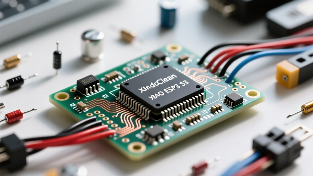
When designing ultra-compact IoT devices, wearables, or edge-AI camera rigs, the Seeed Studio XIAO ESP32S3 is a powerhouse. Measuring just 21 x 17.5mm, it packs a dual-core Xtensa LX7 processor running at 240MHz, native USB, and Wi-Fi/BLE 5.0 capabilities. However, its tiny footprint means every single pad counts. Understanding the exact XIAO ESP32 S3 pinout is critical to avoiding fried components, boot loops, and peripheral communication failures.
In this comprehensive how-to tutorial, we will map every physical pad to its underlying ESP32-S3 GPIO, explore the hidden power delivery circuits, and provide actionable Arduino IDE configuration steps to get your sensors, motors, and cameras running flawlessly.
Visualizing the XIAO ESP32 S3 Pinout
The XIAO ESP32S3 features 14 edge-castellated pads. Unlike larger development boards, the silk screen uses 'D' (Digital) and 'A' (Analog) designations that map to specific underlying GPIOs. Below is the definitive hardware mapping table for the base XIAO ESP32S3 board.
| Pad # | Silk Screen | GPIO | Primary Functions & Notes |
|---|---|---|---|
| 1 | 5V | - | USB VBUS / External 5V Input (Tied to Battery Charge IC) |
| 2 | GND | - | Common Ground |
| 3 | 3V3 | - | Regulated 3.3V Output (Max 600mA draw recommended) |
| 4 | D0 / A0 | GPIO1 | ADC1_CH0, Touch1, PWM capable |
| 5 | D1 / A1 | GPIO2 | ADC1_CH1, Touch2, PWM capable |
| 6 | D2 / A2 | GPIO3 | ADC1_CH2, Touch3 (Internal Strapping Pin - see below) |
| 7 | D3 / A3 | GPIO4 | ADC1_CH3, Touch4, PWM capable |
| 8 | D4 / A4 | GPIO5 | ADC1_CH4, Touch5, PWM capable |
| 9 | D5 / A5 | GPIO6 | ADC1_CH5, Touch6, PWM capable |
| 10 | D6 / A6 | GPIO7 | ADC1_CH6, Touch7, PWM capable |
| 11 | D7 / A7 | GPIO8 | ADC1_CH7, Touch8, Default I2C SCL |
| 12 | D8 / A8 | GPIO9 | ADC1_CH8, Touch9, Default I2C SDA |
| 13 | D9 / TX | GPIO43 | Default UART0 TX (Not ADC capable) |
| 14 | D10 / RX | GPIO44 | Default UART0 RX (Not ADC capable) |
Power Delivery and the Battery Charging Circuit
One of the most significant information gains when working with the XIAO series is understanding its power path. Pad 1 (5V) is directly connected to the USB VBUS line and the input of the onboard SGM4056 lithium battery charging IC. If you connect a Li-Po battery to the hidden BAT pads on the underside of the board, plugging in USB will automatically charge the cell.
Critical Warning: Never inject 5V directly into the 3V3 pad (Pad 3). The 3V3 pad is the output of the onboard LDO regulator. Back-feeding 5V here will instantly destroy the ESP32-S3 silicon and bypass the voltage regulation entirely.
How to Map Pins in the Arduino IDE
To program the XIAO ESP32S3, you must use the official Espressif Arduino Core. The board relies on native USB (via GPIO19 and GPIO20, which are internally routed to the USB-C port), meaning it acts as its own serial converter.
Step 1: Board Manager Configuration
- Open Arduino IDE and navigate to File > Preferences.
- Add the Espressif board manager URL:
https://raw.githubusercontent.com/espressif/arduino-esp32/gh-pages/package_esp32_index.json - Go to Tools > Board > Boards Manager, search for 'esp32', and install the latest version (v2.0.14 or newer recommended for S3 stability).
- Select XIAO_ESP32S3 from the Seeed XIAO menu.
Step 2: Writing Hardware-Agnostic Code
While you can use raw GPIO numbers (e.g., GPIO9), the Seeed variant file includes macros for the silk screen labels. Using these macros makes your code portable across the XIAO SAMD21, RP2040, and ESP32S3 ecosystems.
// Example: Blinking an LED on D0 and reading a potentiometer on A1
#define LED_PIN D0
#define POT_PIN A1

void setup() {
  pinMode(LED_PIN, OUTPUT);
  analogReadResolution(12); // ESP32-S3 ADC is 12-bit (0-4095)
  Serial.begin(115200);
}

void loop() {
  digitalWrite(LED_PIN, HIGH);
  delay(500);
  digitalWrite(LED_PIN, LOW);

  int sensorValue = analogRead(POT_PIN);
  Serial.print('Analog Read: ');
  Serial.println(sensorValue);
  delay(500);
}
Critical Warning: Navigating Strapping Pins
The ESP32-S3 relies on specific 'strapping pins' to determine boot modes and flash voltages during reset. If these pins are pulled to the wrong logic level during power-on, the microcontroller will fail to boot or enter an endless reset loop.
- GPIO0 (Boot Button): Must be HIGH for normal execution. Pulling it LOW during reset forces the chip into USB-DFU download mode.
- GPIO3: Must be HIGH to enable SPI flash boot. (Note: On the XIAO, GPIO3 is mapped to D2/A2. Avoid tying D2 to GND via external hardware during power-up).
- GPIO45 & GPIO46: Control VDD_SPI voltage and boot log output. Fortunately, Seeed Studio has routed these internally to the SPI flash and pull-down resistors. They are not exposed on the edge pads, saving makers from accidental miswiring.
For deeper architectural details on boot modes, refer to the Official ESP32-S3 Datasheet by Espressif.
Wiring the XIAO ESP32S3 Sense (Camera & Mic Add-ons)
If you are using the XIAO ESP32S3 Sense expansion board, the pinout expands dramatically via a 16-pin FPC connector and surface-mount peripherals. The Sense board adds an OV2640 camera and a PDM microphone.
Sense Peripheral Mapping
- PDM Microphone CLK: GPIO42
- PDM Microphone DATA: GPIO41
- Camera DVP Interface: Utilizes GPIO10 through GPIO18, plus GPIO38-GPIO40 for I2C and control signals.
- SD Card Slot: Uses SPI mode on GPIO21 (MOSI), GPIO47 (MISO), GPIO48 (SCK), and GPIO22 (CS).
When initializing the camera in the Arduino IDE, you must use the seeed_xiao_esp32s3 camera pin definition header rather than the standard AI-Thinker or ESP32-CAM definitions, as the DVP routing is entirely unique to the XIAO form factor.
Real-World Troubleshooting: Common Pinout Mistakes
Even experienced engineers run into quirks when adapting to the ESP32-S3 architecture. Here is how to solve the most frequent hardware and software roadblocks.
1. I2C Sensors Failing to Initialize
The ESP32-S3 Arduino core does not always default to the Seeed silk screen I2C pins (D8/D9). If your BME280 or OLED display hangs during Wire.begin(), explicitly declare the SDA and SCL pins based on the physical GPIOs.
#include
// GPIO9 is SDA (D8), GPIO8 is SCL (D7)
Wire.begin(9, 8);
Additionally, the XIAO ESP32S3 lacks internal pull-up resistors on the I2C bus. Always ensure your sensor breakout board has 4.7kΩ pull-ups to 3.3V, or add them externally.
2. Native USB Upload Failures
Because the XIAO ESP32S3 uses native USB (GPIO19/20) instead of a dedicated UART-to-USB bridge chip, the bootloader can occasionally crash and drop the COM port. The Fix: Plug the board into USB while holding down the BOOT button (which pulls GPIO0 low). Tap the RESET button, then release the BOOT button. This forces the ROM bootloader to enumerate as a USB-DFU device, allowing the Arduino IDE to push the new sketch.
3. Analog Read Non-Linearity
While the ESP32-S3 ADC is vastly superior to the notorious non-linear ADC of the original ESP32, it still exhibits slight compression near the 3.3V rail. If you require high-precision voltage measurements, implement a software calibration curve or use an external I2C ADC like the ADS1115 for lab-grade accuracy.
References and Further Reading
- Seeed Studio Wiki: XIAO ESP32S3 Getting Started - Official hardware schematics and variant files.
- Espressif Arduino-ESP32 GitHub Repository - Source code for core pin mapping and native USB drivers.
- Espressif ESP32-S3 Datasheet - Deep dive into strapping pins, RTC domains, and deep-sleep wake-up sources.
By mastering the XIAO ESP32 S3 pinout and respecting the underlying silicon's power and boot requirements, you can reliably deploy this microcontroller into highly constrained, battery-powered environments without sacrificing processing power.