
Redefining the Return Path: What is GND on Arduino?
When makers ask what is GND on Arduino, the standard tutorial answer is usually "it is the zero-volt reference" or "the negative terminal." While this mental model is sufficient for blinking a single LED, it becomes a massive workflow bottleneck as projects scale. Treating Ground (GND) as a magical, infinite sink that absorbs current without consequence is the root cause of roughly 80% of erratic sensor readings, I2C communication drops, and spontaneous microcontroller resets.
From a workflow optimization perspective, understanding GND as a physical return path with inherent resistance and inductance will save you dozens of hours of debugging. Instead of rewriting code to filter out "ghost" noise, you can eliminate the noise at the hardware level before you even open the Arduino IDE.
The Physics of the Ground Trace
According to All About Circuits, ground is simply the common return path for electric current. However, copper has resistance. A standard 22 AWG breadboard jumper wire has a resistance of approximately 16 milliohms (0.016 Ω) per foot. If your ground wire is two feet long (including the internal breadboard traces), you have roughly 0.032 Ω of resistance.
If you are driving a servo motor that pulls 1.5 Amps during startup, Ohm's Law (V = I × R) dictates a voltage drop of 48 millivolts (mV) across that ground wire. If your analog sensor shares that exact same ground path, its "zero" reference just jumped by 48mV. On a classic Arduino Uno R3 with a 10-bit ADC (4.88mV per step), your sensor reading will instantly jump by 10 discrete steps, appearing as severe noise in your Serial Monitor.
Workflow Bottleneck: The Arduino Uno R4 ADC Sensitivity
As of 2026, the widespread adoption of the Arduino Uno R4 Minima and WiFi boards has introduced a new layer of grounding complexity. The R4 series features a 14-bit ADC, yielding a resolution of roughly 0.3mV per step (assuming a 5V reference). While this is a massive upgrade for precision analog workflows, it makes the board exponentially more vulnerable to ground bounce.
A ground bounce of just 3mV—caused by a nearby digital pin switching states or a nearby Wi-Fi transmission on the R4 WiFi—will cause a 10-step jitter in your 14-bit analog readings. Optimizing your grounding topology is no longer optional; it is a mandatory step in the R4 prototyping workflow.
Grounding Topologies: Choosing the Right Workflow
To optimize your build time, select the correct grounding topology based on your project's current draw and signal sensitivity. The table below outlines the three primary topologies used in maker workflows.
| Topology | Description | Best Use Case | Workflow Impact |
|---|---|---|---|
| Daisy Chain | Grounds are connected in a single linear sequence from component to component. | Low-current digital logic (e.g., chaining multiple 74HC595 shift registers). | Fast to wire on a breadboard, but causes severe ground bounce if high-current loads are at the end of the chain. |
| Star Grounding | All ground wires route back to a single, central physical point (usually the Arduino GND pin or a dedicated terminal block). | Mixed-signal circuits (e.g., L298N motor drivers alongside HC-SR04 ultrasonic sensors). | Requires more jumper wires and planning, but entirely eliminates shared-impedance coupling. Highly recommended for robotics. |
| Ground Plane | A solid, continuous sheet of copper acting as the ground return (used in custom PCBs). | High-frequency RF designs (e.g., ESP32 LoRa nodes, high-speed SPI). | Eliminates breadboard parasitic inductance. Essential for moving from prototype to final PCB manufacturing. |
The "Pre-Code" Grounding Optimization Checklist
Stop blaming your C++ code for hardware flaws. Integrate this checklist into your physical prototyping workflow before you write your setup() and loop() functions. For a deeper dive into physical prototyping layouts, refer to the Arduino Breadboard Basics guide.
- Separate High and Low Current Returns: Never route the ground return of a relay module or DC motor through the Arduino's onboard GND header. Route the motor's ground directly back to the power supply's ground terminal, and connect that terminal to the Arduino GND at a single point (Star Topology).
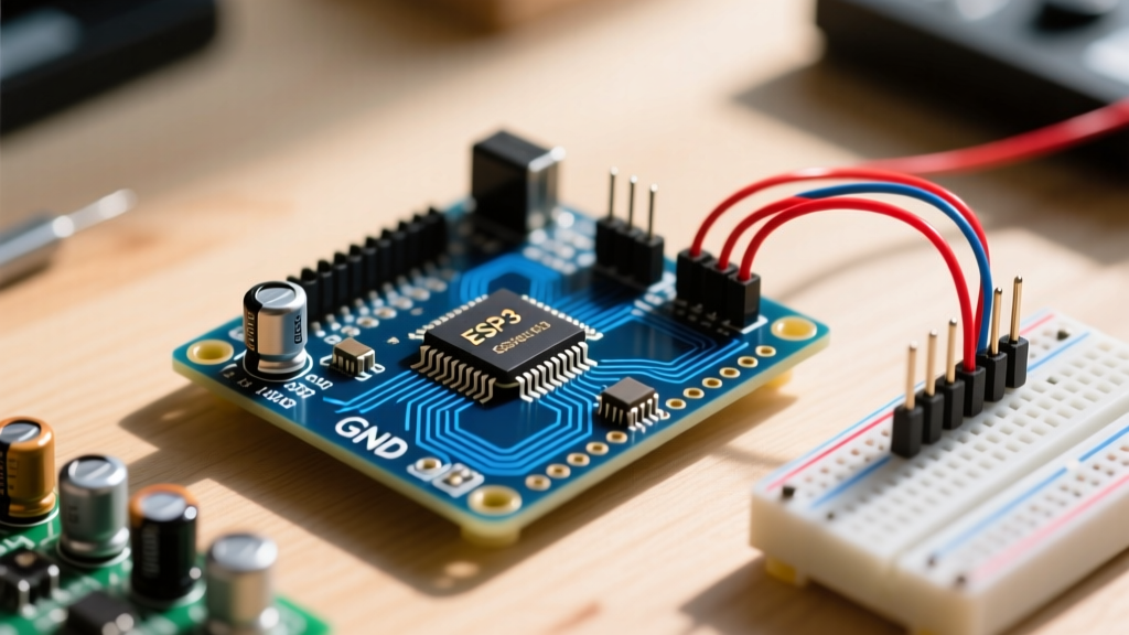
- Verify Common Grounds for Multi-Board Setups: If you are connecting an Arduino to an ESP32 via UART (TX/RX), you must connect their GND pins together. Without a common ground reference, the voltage thresholds for logic HIGH and LOW will float, resulting in corrupted serial data.
- Use Thicker Wires for Power/Ground: Swap out standard 28 AWG breadboard jumper wires for 22 AWG or 20 AWG silicone wires for all power and ground rails. This reduces resistance by over 75%, minimizing voltage drop.
- Implement Local Decoupling: Place a 0.1 µF ceramic capacitor as close to the VCC and GND pins of external ICs (like the MCP23017 I/O expander) as physically possible. This provides a localized high-frequency current reservoir, preventing transient spikes from traveling through the main ground rail.
Workflow Pro-Tip: When wiring an L298N motor driver to an Arduino, always connect the L298N's GND terminal to both the external motor power supply's negative terminal and the Arduino's GND pin. Skipping the Arduino GND connection is the #1 cause of PWM speed control failure in student and hobbyist robotics projects.
Advanced Debugging: Measuring Ground Bounce
If you have optimized your physical layout but are still seeing ADC jitter or I2C NACK errors, it is time to measure the ground plane integrity. Do not rely on visual inspection; use your tools.
The Multimeter Method (DC Drop)
Set your digital multimeter (DMM) to the millivolt (mV) DC range. Place the black probe directly on the Arduino's metal USB shield (which is tied to the primary ground plane) and the red probe on the GND pin of your external sensor while the circuit is under full load. If you read more than 10mV to 20mV of DC voltage drop, your ground wire is too thin or too long. Upgrade the wire gauge immediately.
The Oscilloscope Method (AC Noise)
For high-frequency noise (ground bounce caused by digital switching), a DMM is too slow. Use an oscilloscope with the probe's ground clip attached to the Arduino GND, and the probe tip touching the same GND rail a few inches away. Set the scope to AC coupling and a sensitive scale (e.g., 5mV/div). You will likely see high-frequency spikes coinciding with your microcontroller's clock cycles or PWM switching. If these spikes exceed your ADC's LSB (Least Significant Bit) voltage, you must implement software oversampling or add an RC low-pass filter to your analog inputs.
When to Use Galvanic Isolation
Sometimes, optimizing the ground path isn't enough. If your workflow involves switching high-voltage AC loads (like mains-powered heaters) or dealing with heavy industrial inductive loads, sharing a ground with the Arduino is a catastrophic risk to both the hardware and the user. In these scenarios, abandon the shared ground entirely.
Utilize optocouplers (like the PC817) or digital isolators (like the ISO7721) to transmit signals across an optical or magnetic barrier. This completely breaks the electrical continuity of the ground path, protecting your low-voltage microcontroller workflow from high-voltage ground faults and massive inductive kickback spikes.
Summary: Hardware First, Code Second
Understanding what GND is on an Arduino—and more importantly, what it isn't—is the hallmark of an efficient maker workflow. By treating ground as a physical, imperfect conductor and applying star-topology routing, proper wire gauging, and localized decoupling, you eliminate the vast majority of "unexplainable" software bugs. Optimize your electrons first, and your code will naturally follow.
For further reading on managing complex electronic grounds, review DigiKey's comprehensive guide on grounding in electronic designs, which details PCB-level strategies that translate well to advanced breadboard prototyping.