
The Reality of Analog Inputs: Why Your Pot Arduino Setup Jitters
Connecting a potentiometer (pot) to an Arduino seems like the most straightforward task in electronics: wire the outer pins to 5V and GND, and the wiper to an analog pin. However, makers frequently encounter a frustrating reality—the serial monitor outputs a jittery stream of values even when the knob is perfectly still. This 'pot Arduino' configuration issue is rarely a defect in the microcontroller; rather, it is a combination of electromagnetic interference (EMI), breadboard parasitic capacitance, and the inherent thermal noise of the ADC (Analog-to-Digital Converter).
In this comprehensive configuration guide, we will move beyond the basic 3-wire tutorial. We will explore how to select the correct taper, design a hardware RC low-pass filter, implement software oversampling, and calibrate your setup for industrial-grade precision on both legacy ATmega328P boards and modern Renesas RA4M1-based Arduino Uno R4 models.
Choosing the Right Potentiometer for Microcontroller ADCs
Not all potentiometers are created equal. Selecting the wrong taper or resistance value will cripple your ADC resolution before a single line of code is written.
| Specification | Linear Taper (B10K) | Audio Taper (A10K) | Multi-Turn Precision (Bourns 3590S) |
|---|---|---|---|
| Resistance Profile | Linear (Equal change per degree) | Logarithmic (Clusters at low end) | Linear (10 turns for full sweep) |
| ADC Mapping | Direct linear mapping (Easy) | Requires complex lookup tables | High-resolution linear mapping |
| Typical Cost (2026) | $0.50 - $1.20 | $0.80 - $1.50 | $12.00 - $18.00 |
| Best Use Case | Standard user inputs, motor speed | Audio volume (Avoid for MCU ADCs) | Lab equipment, precision calibration |
Expert Rule: Always choose a B-prefix (Linear) potentiometer for microcontroller analog inputs. Audio taper (A-prefix) pots use a logarithmic curve designed for human hearing perception. If fed into an Arduino's linear ADC, 80% of your physical knob rotation will result in only 20% of the ADC value range, destroying your effective resolution. For standard projects, a 10KΩ linear pot is ideal because it perfectly matches the Arduino analogRead() source impedance recommendations, which suggest keeping the input impedance under 10kΩ to allow the internal sample-and-hold capacitor to charge fully.
Hardware Configuration: Beyond the Basic 3-Wire Connection
The most common point of failure in a pot Arduino circuit is ground bounce and high-frequency noise injection. If your Arduino is simultaneously driving a motor via an H-bridge or switching relays, the transient current spikes on the ground rail will modulate the ground reference of your potentiometer, causing massive ADC jitter.
Implementing the RC Low-Pass Filter
To eliminate EMI and high-frequency noise, you must add a hardware low-pass filter between the pot wiper and the Arduino analog pin. A simple first-order RC filter is highly effective.
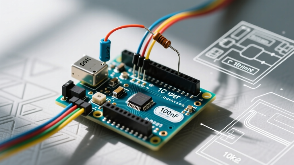
- Resistor (R): 100Ω (Placed in series between the wiper and the analog pin)
- Capacitor (C): 100nF (0.1µF) MLCC X7R ceramic capacitor (Placed between the analog pin and GND)
The Math: The cutoff frequency ($f_c$) is calculated as $f_c = 1 / (2 \pi R C)$. With a 100Ω resistor and a 100nF capacitor, your cutoff frequency is approximately 15.9 kHz. This aggressively filters out radio frequency interference and switching noise from DC-DC converters, while allowing the physical turning of the knob (which occurs at less than 5 Hz) to pass through with zero perceptible latency.
Star Grounding for Mixed-Signal Boards
Never share the same breadboard ground row for your high-current loads and your analog sensors. Run a dedicated ground wire directly from the potentiometer's ground pin to one of the Arduino's GND pins. According to SparkFun's Analog to Digital Conversion guidelines, maintaining a clean analog ground reference is critical for preserving the effective number of bits (ENOB) of your ADC.
Software Configuration: Oversampling and Digital Filtering
Even with perfect hardware, the ADC quantization process introduces a small amount of white noise. We solve this in software using an Exponential Moving Average (EMA) filter combined with oversampling.
The EMA Smoothing Algorithm
Instead of using a simple delay-based averaging loop (which blocks the main thread and ruins real-time performance), use an EMA filter. It requires only one floating-point variable and executes in microseconds.
// EMA Filter Configuration
float smoothedValue = 0.0;
const float alpha = 0.15; // Smoothing factor (0.0 to 1.0)

void setup() {
  Serial.begin(115200);
  analogReadResolution(10); // Explicitly set 10-bit for Uno R3/R4 consistency
}

void loop() {
  int rawReading = analogRead(A0);

  // EMA Calculation
  smoothedValue = (alpha * rawReading) + ((1.0 - alpha) * smoothedValue);

  Serial.println((int)smoothedValue);
  // No delay needed; non-blocking and highly responsive
}
Tuning the Alpha Value: An alpha of 0.15 provides a buttery-smooth output ideal for motor speed control or LED dimming. If you are building a fast-paced game controller where latency matters more than absolute smoothness, increase alpha to 0.40. If your display is still flickering, drop it to 0.05, but expect a slight physical lag when turning the knob rapidly.
Calibration Matrix: Mapping Raw ADC to Physical Degrees
Potentiometers rarely output exactly 0 at one extreme and 1023 (or 4095 on 12-bit systems) at the other. Mechanical end-stops and wiper resistance create 'dead zones'. To configure your software properly, you must map the usable range.
| Physical Position | Raw 10-bit ADC (Ideal) | Real-World Measured (Typical) | Mapped Output (0-100%) |
|---|---|---|---|
| Full Counter-Clockwise | 0 | 12 - 25 | 0% |
| Center Detent (if applicable) | 512 | 505 - 518 | 50% |
| Full Clockwise | 1023 | 998 - 1015 | 100% |
Use the Arduino map() function with your real-world measured boundaries, and always wrap it in a constrain() function to prevent out-of-bounds errors when the user forcefully turns the knob past its mechanical limits.
int raw = analogRead(A0);
int calibrated = map(raw, 20, 1005, 0, 255);
calibrated = constrain(calibrated, 0, 255); // Prevents negative or >255 values
Advanced Edge Cases and Failure Modes
When deploying a pot Arduino setup in harsh environments or permanent installations, be aware of these specific failure modes:
- Wiper Oxidation (Carbon Track Pots): Standard carbon-composition pots (like the Alpha RV16 series) are prone to wiper oxidation over time, causing sudden 'dropouts' where the ADC reads 0 or 1023 momentarily. Solution: Upgrade to Cermet (Ceramic-Metal) or Conductive Plastic pots. The Bourns Potentiometer Product Line offers excellent cermet alternatives (like the 3386 series) that resist oxidation and maintain contact integrity over 100,000+ cycles.
- Thermal Drift: Carbon pots have a high temperature coefficient of resistance (TCR), often ±1000 ppm/°C. If your Arduino enclosure heats up (e.g., from onboard voltage regulators), the total resistance of the pot will shift. Because the ADC measures the *ratio* of the voltage divider rather than absolute resistance, thermal drift of the resistive element itself is mostly canceled out. However, if the wiper contact resistance changes with heat, ratio-metric errors will occur.
- Over-voltage Injection: Never power a potentiometer with a voltage higher than your microcontroller's logic level. If you are using a 3.3V Arduino (like the Due or Nano 33 IoT), powering the pot with 5V will instantly destroy the ADC input pin's internal clamping diodes when the wiper is turned past the 3.3V threshold.
Frequently Asked Questions
Can I use a 100K potentiometer to save battery power?
While a 100K pot draws only 50µA at 5V (compared to 500µA for a 10K pot), it violates the ATmega328P's 10kΩ recommended source impedance limit. The internal sample-and-hold capacitor (approx. 14pF) will not have enough time to charge to the correct voltage during the ADC conversion clock cycles, resulting in severe non-linearity and dropped readings. If you must use high-resistance pots to save power, you must add an op-amp voltage follower (buffer) between the wiper and the Arduino analog pin.
Why does my Arduino Uno R4 read differently than my Uno R3?
The Uno R3 uses the ATmega328P with a native 10-bit ADC (values 0-1023). The Uno R4 uses the Renesas RA4M1, which features a 14-bit ADC. By default, the Arduino core maps the R4's ADC to 10-bit for backward compatibility. If you want the extra precision for your pot configuration, add analogReadResolution(14); in your setup function to unlock values from 0-16383, drastically reducing the need for software oversampling.
How do I fix a 'dead spot' in the middle of my potentiometer's rotation?
A dead spot where the value refuses to change usually indicates physical wear on the carbon track or a buildup of insulating debris inside the housing. If it is a sealed unit, it must be replaced. If it is an open-frame trimmer, a single drop of specialized electronic contact cleaner (like DeoxIT D5) applied directly to the wiper track can dissolve the oxidation and restore smooth analog tracking.