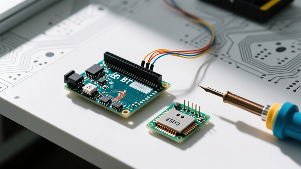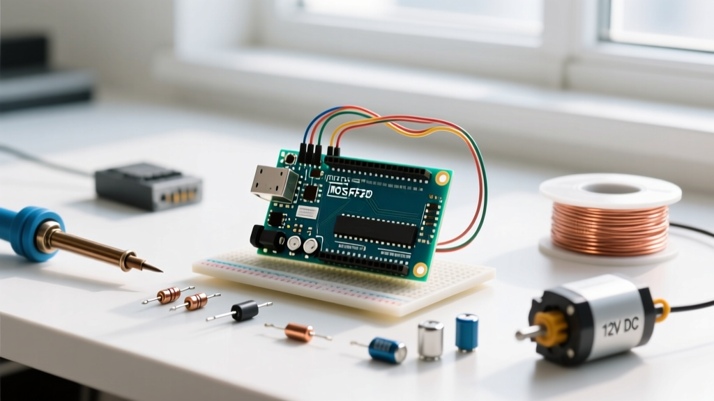

Why Migrate from Relays and BJTs to an Arduino with MOSFET Switches?
As microcontroller projects evolve from simple LED blinkers to high-power automation systems, makers inevitably hit the current limits of standard digital I/O pins. An Arduino Uno or Mega can safely source or sink only about 20mA per pin, with an absolute maximum of 40mA. Attempting to drive motors, high-power LED strips, or heating elements directly will destroy the ATmega328P silicon. Historically, beginners migrated to electromechanical relays or Bipolar Junction Transistors (BJTs) like the 2N2222. However, as we move through 2026, upgrading to an Arduino with MOSFET (Metal-Oxide-Semiconductor Field-Effect Transistor) configurations has become the industry standard for solid-state switching.
MOSFETs offer near-infinite input impedance, meaning they draw virtually zero continuous current from your microcontroller's GPIO pins. Unlike mechanical relays, they have no moving parts, produce no acoustic noise, and can switch at frequencies exceeding 100kHz—making them mandatory for PWM (Pulse Width Modulation) dimming and motor speed control. This migration guide provides a comprehensive blueprint for transitioning your high-power loads from legacy switching methods to modern, logic-level MOSFET architectures.
Component Comparison Matrix: BJT vs. Relay vs. MOSFET
Before ripping out your existing relay modules, it is crucial to understand the operational trade-offs. The table below compares the three primary switching methods used in maker electronics.
| Feature | 2N2222 (NPN BJT) | 5V Electromechanical Relay | Logic-Level MOSFET (IRLB8721) |
|---|---|---|---|
| Max Continuous Current | ~800mA | 10A - 30A | 62A (at 25°C case temp) |
| Drive Current Required | High (Base current needed) | High (~70mA for coil) | Near Zero (Voltage-driven) |
| Switching Speed | Fast (~100ns) | Very Slow (~10ms) | Extremely Fast (~10ns - 50ns) |
| PWM Compatibility | Yes (with limits) | No (causes contact arcing) | Excellent (Ideal for PWM) |
| Voltage Drop (On-State) | ~0.2V (Vce_sat) | Negligible (Contact resistance) | Millivolts (Based on Rds_on) |
| Approx. Unit Cost (2026) | $0.15 | $1.50 (Module) | $0.85 (TO-220 package) |
The 'Logic-Level' Trap: Selecting the Correct MOSFET
The most common point of failure when integrating an Arduino with MOSFET circuits is selecting the wrong transistor family. MOSFETs are categorized by their Gate-to-Source Threshold Voltage ($V_{GS(th)}$) and their full enhancement voltage. Many beginners purchase the infamous IRF520 or IRF540 because they are cheap and widely available on pre-made breakout boards. This is a critical mistake.
The IRF series are standard-level MOSFETs designed for 10V to 12V gate drive environments (like ATX power supplies or automotive systems). While an IRF520 might begin to turn on at a $V_{GS(th)}$ of 2.0V to 4.0V, it will not fully enhance (reach its lowest $R_{DS(on)}$ resistance) until the gate receives 10V. If you drive an IRF520 with a 5V Arduino pin, the transistor operates in its linear (ohmic) region, acting as a massive resistor. This results in severe voltage drops, extreme heat generation, and eventual thermal runaway.
Expert Rule of Thumb: For 5V Arduinos (Uno, Mega, Nano), you must use Logic-Level MOSFETs, typically denoted by an 'L' in the prefix (e.g., IRLB8721, IRLZ44N). For 3.3V Arduinos (Due, Portenta, ESP32), you need ultra-low threshold MOSFETs like the TI CSD18540Q5B, which fully enhance at $V_{GS}$ = 2.5V. Always consult the datasheet's '$R_{DS(on)}$ vs $V_{GS}$' graph, not just the threshold voltage.
For deeper reading on semiconductor switching characteristics, the Electronics Tutorials guide on MOSFETs as switches provides excellent foundational physics on channel enhancement and depletion regions.
Step-by-Step Migration Blueprint
Transitioning from a relay module to a bare MOSFET requires adding a few passive components to protect both your microcontroller and the transistor. Do not simply wire the gate directly to the Arduino digital pin.
1. Gate Drive and Protection Resistors
A MOSFET gate behaves like a small capacitor (often between 1000pF and 4000pF). When the Arduino pin goes HIGH, it must charge this capacitor instantly. This initial inrush current can exceed the 20mA safe limit of the ATmega328P I/O pin, potentially degrading the silicon over time. Furthermore, the parasitic inductance of your breadboard or PCB traces can combine with the gate capacitance to create high-frequency ringing, leading to EMI (Electromagnetic Interference) and erratic switching.
- Gate Series Resistor ($R_G$): Place a 100Ω to 220Ω resistor between the Arduino digital pin and the MOSFET gate. This limits the inrush current and dampens high-frequency ringing.
- Gate Pull-Down Resistor ($R_{PD}$): Place a 10kΩ resistor between the MOSFET gate and ground (GND). During the Arduino's boot sequence, I/O pins float in a high-impedance state. Without a pull-down resistor, ambient static charge can turn the MOSFET partially on, leading to unpredictable load behavior or destruction.
2. Managing Inductive Kickback
If your Arduino with MOSFET setup is driving an inductive load—such as a DC motor, solenoid, or water pump—you must include a flyback diode. When the MOSFET switches off, the collapsing magnetic field in the inductor generates a massive reverse voltage spike (often exceeding 100V) that will instantly punch through the MOSFET's drain-source junction.
- Diode Selection: Use a Schottky diode (like the SS34 or 1N5819) for high-frequency PWM applications due to their fast recovery times. For slow-switching applications (like a water pump turning on once an hour), a standard 1N4007 rectifier diode is sufficient.
- Placement: Wire the diode in reverse bias across the load (cathode to the positive supply, anode to the MOSFET drain).
For official specifications regarding Arduino pin current sourcing limits and absolute maximum ratings, refer to the Arduino Digital Pins documentation.
Thermal and Power Calculations for 2026 Designs
One of the greatest advantages of upgrading to an Arduino with MOSFET architectures is the incredibly low on-state resistance ($R_{DS(on)}$), which dictates how much power the transistor wastes as heat. Let us run a real-world thermal calculation using the highly recommended IRLB8721PbF (Infineon), a staple in the maker community.
Suppose you are driving a 12V LED strip that draws 10 Amps of continuous current. The IRLB8721 has an $R_{DS(on)}$ of roughly 8.5mΩ (0.0085Ω) when driven with a 4.5V gate signal.
Power Dissipation Formula: $P = I^2 \times R_{DS(on)}$
$P = (10A)^2 \times 0.0085\Omega = 100 \times 0.0085 = 0.85 Watts$
A standard TO-220 package can safely dissipate about 2.0W to 2.5W in free air (without a heatsink) before the junction temperature reaches dangerous levels. At 0.85W, the IRLB8721 will run warm to the touch (around 60°C) but is perfectly safe without a heatsink. Compare this to a BJT like the TIP120, which has a $V_{CE(sat)}$ of roughly 2V at 10A. The TIP120 would dissipate $P = 10A \times 2V = 20 Watts$, instantly requiring a massive heatsink and active cooling. This stark contrast highlights why MOSFETs have entirely replaced Darlington BJTs in modern high-power maker designs.
Cost Analysis: Is the Bare MOSFET Upgrade Worth It?
Many hobbyists rely on pre-packaged 'MOSFET Switch Modules' sold on Amazon or AliExpress for $3.00 to $5.00. However, as of 2026, supply chain stabilizations mean you can build a vastly superior, custom-tailored MOSFET circuit on a perfboard or custom PCB for a fraction of the cost. Sourcing an authentic Infineon IRLB8721 from authorized distributors like Mouser or DigiKey costs approximately $0.85 to $1.10 in single quantities. Add a $0.02 gate resistor, a $0.02 pull-down resistor, and a $0.05 Schottky diode, and your total BOM (Bill of Materials) for the switching stage is under $1.10. Furthermore, building it yourself guarantees you aren't receiving counterfeit silicon, a prevalent issue with cheap, unbranded relay and MOSFET modules.
Frequently Asked Questions
Can I use an IRF520 module with a 3.3V Arduino or ESP32?
No. The IRF520 requires 10V on the gate to fully turn on. At 3.3V, it will barely conduct, resulting in massive voltage drops and immediate overheating. For 3.3V logic environments, migrate to modern NexFETs or Trench MOSFETs like the Texas Instruments CSD17885F5 or the Alpha & Omega AON7408, which exhibit ultra-low $R_{DS(on)}$ at $V_{GS}$ = 2.5V.
Do I need a dedicated Gate Driver IC for my Arduino with MOSFET setup?
For low-frequency switching (under 5kHz) and standard loads, the Arduino GPIO pin can charge the gate capacitor fast enough through a 100Ω resistor. However, if you are designing a high-frequency PWM motor controller (20kHz+) or driving MOSFETs with massive gate capacitance (like those in D2PAK packages rated for 100A+), you must use a dedicated gate driver IC (such as the Microchip MCP1402 or TC4420) to supply the peak current required to switch the gate in nanoseconds.
What happens if I wire the MOSFET backward?
Unlike BJTs, power MOSFETs contain an intrinsic 'body diode' between the drain and source. If you accidentally reverse the drain and source connections, the body diode will become forward-biased, and current will flow continuously through the load, completely bypassing your Arduino's control. The MOSFET will not be damaged, but your load will remain permanently powered on.