
The Legacy 5V Era vs. Modern 32-Bit Architectures
For over a decade, the ATmega328P-based Arduino Uno R3 was the undisputed baseline for microcontroller projects. In that environment, digitalRead() was a simple, foolproof function. You set a pin to INPUT or INPUT_PULLUP, called the function, and received a clean HIGH or LOW. However, as of 2026, the maker and professional prototyping landscape has aggressively shifted toward 32-bit ARM Cortex-M boards (like the Arduino Uno R4 and Teensy 4.1) and dual-core Xtensa/LX7 architectures (like the ESP32-S3).
Migrating legacy sketches to these modern platforms is rarely a simple copy-paste job. The underlying hardware abstraction layers (HAL), voltage logic thresholds, and real-time operating system (RTOS) constraints fundamentally change how digitalRead() behaves. This guide provides a deep-dive migration framework for upgrading your digital input routines, avoiding hardware traps, and optimizing execution latency on modern silicon.
Voltage Logic Level Shifts: The 5V to 3.3V Migration
The most immediate hardware failure point when migrating arduino digitalread routines is the shift from 5V to 3.3V logic. On the legacy ATmega328P, the input high voltage threshold (Vih) was roughly 0.6 × VCC, meaning any signal above 3.0V registered as HIGH.
Modern 3.3V microcontrollers have different threshold requirements:
- ESP32-S3: Vih is typically 0.75 × VCC (approx. 2.47V). While it is 5V tolerant on most pins, feeding it a 3.3V signal from a legacy sensor might hover dangerously close to the threshold if there is voltage sag.
- Renesas RA4M1 (Arduino Uno R4): Operates strictly at 3.3V. Applying 5V to a GPIO without a level shifter will permanently damage the port register.
- RP2040 (Raspberry Pi Pico): Vih is 0.7 × VCC (approx. 2.31V), but absolute maximum ratings strictly forbid 5V inputs.
Migration Action Item: Before uploading migrated code, audit your circuit. If your legacy sketch relied on 5V open-collector outputs pulling up to 5V, you must insert a bidirectional logic level converter (like the Texas Instruments TXS0108E, costing around $1.50 per IC) or use a simple voltage divider (e.g., 2.2kΩ and 3.3kΩ resistors) to scale the signal down to 3.3V.
ESP32 GPIO Matrix and Input-Only Pin Traps
When migrating to the ESP32 ecosystem, developers frequently encounter erratic digitalRead() behavior because they misunderstand the ESP32's GPIO Matrix. Unlike the ATmega328P, where every pin behaves largely identically, the ESP32 routes signals through a complex internal multiplexer.
The most common migration error involves GPIO 34, 35, 36 (VP), and 39 (VN). On the original ESP32, these are input-only pins. Crucially, they do not possess internal pull-up or pull-down resistors.
If your legacy Uno sketch used:
pinMode(34, INPUT_PULLUP);
int state = digitalRead(34);
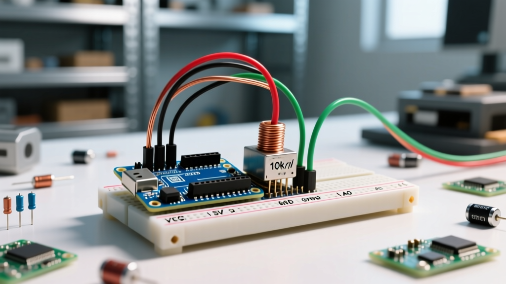
On an ESP32, the INPUT_PULLUP flag is silently ignored by the hardware. The pin will float, picking up electromagnetic interference (EMI) and causing digitalRead() to flicker wildly between 0 and 1. To fix this, you must add an external 10kΩ physical pull-up resistor to 3.3V when migrating to these specific pins.
Internal Pull Resistor Architecture Comparison
When relying on INPUT_PULLUP or INPUT_PULLDOWN, the internal resistance values vary wildly across architectures. This affects your circuit's current draw and noise immunity. Below is a comparison of internal resistor characteristics across popular 2026 development boards.
| Microcontroller | Board Example | Pull-Up Resistance | Pull-Down Support | Migration Note |
|---|---|---|---|---|
| ATmega328P | Arduino Uno R3 | 20kΩ - 50kΩ | No | Legacy baseline. Susceptible to noise in high-EMI environments. |
| ESP32 (Xtensa) | ESP32 DevKit V4 | ~45kΩ | Yes (except GPIO 34-39) | Use INPUT_PULLDOWN for active-high sensors. |
| RP2040 | Raspberry Pi Pico | ~50kΩ - 80kΩ | Yes | High resistance; use external 10kΩ for long wire runs. |
| Renesas RA4M1 | Arduino Uno R4 Minima | ~20kΩ - 50kΩ | Yes | Configurable via Port Function Select (PFS) registers. |
RTOS Environments: The Task Watchdog Trap
Modern microcontrollers like the ESP32 and advanced ARM boards run a Real-Time Operating System (FreeRTOS) under the hood of the Arduino core. This introduces a massive software-level pitfall for legacy digitalRead() polling loops.
In the bare-metal AVR days, waiting for a button press was done via a blocking while-loop:
while(digitalRead(BUTTON_PIN) == HIGH) {
  // Wait for button press
}
Do not do this on an ESP32 or RTOS-enabled ARM board. FreeRTOS requires the IDLE task to run periodically to feed the Task Watchdog Timer (TWDT) and perform memory cleanup. A tight while() loop polling digitalRead() starves the IDLE task, causing the TWDT to trigger a hard reset within seconds. You will see the following error in your serial monitor:
"E (12345) task_wdt: Task watchdog got triggered. The following tasks did not reset the watchdog in time..."
The RTOS Migration Solution
To upgrade this pattern, you must either yield to the scheduler or, preferably, migrate to an interrupt-driven architecture.
Option 1: Yielding (Quick Fix)
while(digitalRead(BUTTON_PIN) == HIGH) {
  vTaskDelay(10 / portTICK_PERIOD_MS); // Yields to RTOS
}
Option 2: Interrupts with Queues (Professional Standard)
Instead of polling digitalRead(), use attachInterrupt() to push an event to a FreeRTOS queue. This consumes zero CPU cycles while waiting and guarantees sub-millisecond latency.
Execution Speed: HAL Abstraction vs. Direct Registers
As projects scale, the execution time of arduino digitalread becomes a bottleneck. The standard Arduino HAL (Hardware Abstraction Layer) performs pin mapping, validates pin numbers, and translates logical pins to physical hardware ports. This overhead is negligible for reading a pushbutton, but catastrophic for high-speed data acquisition (e.g., reading a 1MHz digital bus or software-based SPI).
Latency Benchmarks (2026 Core Versions)
- ATmega328P (Uno R3):
digitalRead()takes approximately 3.5 µs. Direct port read (PIND & (1< - ESP32-S3:
digitalRead()takes approximately 0.8 µs. Direct register read viaGPIO.intakes 0.02 µs (40x faster). - Renesas RA4M1 (Uno R4):
digitalRead()takes approximately 1.2 µs. Direct read via Port registers takes 0.05 µs.
For a comprehensive look at standard function overhead, refer to the official Arduino digitalRead Reference. If your migration requires reading high-frequency pulses, abandon the HAL entirely. On the ESP32, read the entire 32-bit GPIO bank instantly using uint32_t states = GPIO.in;. On the RP2040, read the sio_hw->gpio_in register. For detailed ESP32 register mapping, consult the Espressif ESP-IDF GPIO API documentation.
Advanced Migration: Debouncing in the Modern Era
Legacy sketches often relied on delay(50) to debounce mechanical switches after a digitalRead() state change. In a modern 32-bit environment running Wi-Fi stacks or display refresh loops, a 50ms blocking delay is unacceptable.
When upgrading, implement non-blocking software debouncing using a timestamp comparison, or offload it to hardware. The ESP32-S3 and Renesas RA4M1 both feature hardware programmable filter registers that can automatically debounce GPIO inputs before the signal ever reaches the CPU. Utilizing the Arduino Uno R4 WiFi Cheat Sheet and hardware-specific libraries allows you to configure digital filters directly in the pin setup phase, completely eliminating the need for software delay loops.
Summary Checklist for Upgrading Digital Inputs
- Audit Voltage Levels: Ensure all external signals are scaled to 3.3V.
- Verify Pin Capabilities: Check for input-only pins lacking internal pull resistors (e.g., ESP32 GPIO 34-39).
- Eliminate Blocking Polls: Replace
while(digitalRead())loops with RTOS delays or hardware interrupts. - Optimize High-Speed Reads: Bypass the HAL and use direct register reads for signals exceeding 10 kHz.
- Implement Hardware Debouncing: Leverage 32-bit digital filter registers instead of
delay()functions.
Migrating your arduino digitalread routines to modern architectures requires shifting your mindset from simple 5V bare-metal polling to a holistic understanding of 3.3V logic, RTOS scheduling, and hardware-specific GPIO matrices. By applying these upgrade strategies, your projects will achieve higher reliability, lower latency, and professional-grade stability.