
The 10-Bit Bottleneck: Why Internal ADCs Fail Precision Tasks
Every electronics hobbyist eventually uses an Arduino as a voltmeter. The classic tutorial involves wiring a voltage divider to an analog pin and calling analogRead(). While this is perfect for checking if a battery is roughly half-empty, it falls apart the moment you need true metrology-grade precision. The ATmega328P microcontroller at the heart of the Arduino Uno features a 10-bit Successive Approximation Register (SAR) ADC. Theoretically, this gives you 1,024 discrete steps. With a 5V reference, each step represents 4.88mV.
However, theory ignores silicon reality. According to the Microchip ATmega328P datasheet, the absolute accuracy of the internal ADC is ±2 LSB (Least Significant Bits). Furthermore, when powered via USB, the VCC rail is notoriously noisy, often fluctuating by 50mV or more. Because the internal ADC defaults to using VCC as the voltage reference, your '5.000V' reference might actually be 4.75V on a Tuesday and 5.12V on a Wednesday. To transform your Arduino from a toy into a reliable bench instrument, you must migrate to an external, precision ADC.
Migration Matrix: Internal vs. External ADCs
When upgrading your Arduino as a voltmeter, you have three primary hardware paths. The table below compares the baseline internal ADC with the two most popular I2C external upgrades available in 2026.
| Feature | Internal ATmega328P | TI ADS1115 (16-Bit) | Microchip MCP3424 (18-Bit) |
|---|---|---|---|
| Resolution | 10-bit (1024 steps) | 16-bit (65536 steps) | 18-bit (262144 steps) |
| Effective Number of Bits (ENOB) | ~8.5 bits | ~15.2 bits | ~16.5 bits |
| Max Sample Rate | 15 kSPS | 860 SPS | 240 SPS (at 18-bit) |
| Voltage Reference | VCC or Internal 1.1V | Internal Precision | Internal Precision |
| Typical Breakout Price (2026) | $0 (Built-in) | $4.50 - $8.00 | $12.00 - $16.00 |
| Best Use Case | Rough battery monitoring | General bench multimeter | High-res strain gauges/thermocouples |
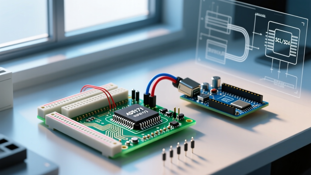
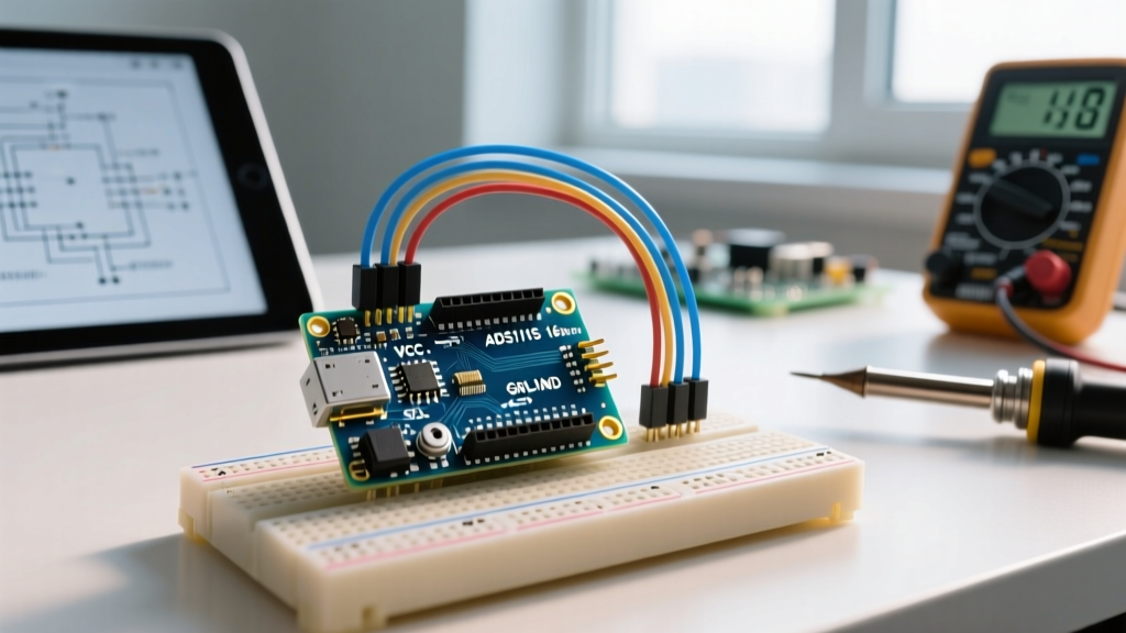
For 90% of makers building a custom voltmeter, the Texas Instruments ADS1115 is the undisputed sweet spot. It offers a massive leap in resolution, includes a programmable gain amplifier (PGA), and operates on a standard I2C bus.
Hardware Design: Building a Bulletproof Front-End
Simply soldering an ADS1115 breakout board to your Arduino does not guarantee precision. The ADC is only as good as the analog front-end feeding it. If you are building a 0-20V DC voltmeter, you must design a protection and scaling network.
1. The Precision Voltage Divider
Do not use standard 5% carbon film resistors for your voltage divider. A 5% tolerance on a 100kΩ resistor introduces massive gain errors that no amount of software calibration can fully fix across temperature ranges. Upgrade to 0.1% tolerance thin-film resistors (such as Susumu RR05 or Vishay Z-Foil series). They cost roughly $0.30 to $0.80 each on DigiKey but are mandatory for a stable Arduino voltmeter.
2. Input Protection and Filtering
The ADS1115 analog inputs are sensitive to overvoltage and electrostatic discharge (ESD). Implement the following protection circuit on your input trace:
- Series Current Limiter: Place a 10kΩ resistor in series with the input signal. This limits fault current to safe levels if the user accidentally probes a 120V AC mains line.
- Clamping Diodes: Use a 5.1V Zener diode (e.g., BZX55C5V1) tied from the ADC input to ground. This ensures the voltage never exceeds the ADS1115's VDD + 0.3V absolute maximum rating.
- RC Low-Pass Filter: Add a 100nF X7R ceramic capacitor in parallel with the Zener diode. Combined with the 10kΩ series resistor, this creates a low-pass filter with a cutoff frequency of roughly 160Hz, effectively eliminating high-frequency switching noise from nearby SMPS power supplies.
Pro-Tip: Never route I2C traces parallel to analog signal traces on your custom PCB or perfboard. The digital edge transitions of the SCL clock line will capacitively couple into your high-impedance analog lines, manifesting as a 100kHz noise floor on your voltmeter readout.
Software Migration: Ditching analogRead()
Migrating your codebase requires replacing blocking analogRead() calls with I2C transactions. The Adafruit_ADS1X15 library remains the industry standard for this migration in the Arduino ecosystem.
Step-by-Step Code Refactoring
- Initialize the I2C Bus: Ensure your
Wire.begin()is called in the setup. If your I2C wires exceed 30cm, you must add 4.7kΩ physical pull-up resistors to SDA and SCL, and consider increasing the I2C clock speed to 400kHz viaWire.setClock(400000). - Configure the PGA: The ADS1115 features a Programmable Gain Amplifier. For a standard 0-5V voltmeter, set the gain to
GAIN_ONE, which configures the Full Scale Range (FSR) to ±4.096V. This yields a resolution of 0.125mV per bit. - Implement Non-Blocking Reads: Unlike
analogRead(), I2C takes time. Use thestartADCReading()andreadADC_SingleEnded()methods to prevent freezing your OLED display update loops while waiting for the ADC to complete its sigma-delta conversion.
The Free Alternative: Software Oversampling
If you are constrained by budget and cannot procure an ADS1115, you can artificially increase the resolution of the internal 10-bit ADC using software oversampling. As detailed in the Analog Devices MT-001 Tutorial, adding intentional dither noise and oversampling by a factor of 4 yields one additional bit of resolution. To achieve 12-bit resolution from your Uno's internal ADC, you must sample the pin 16 times, sum the results, and bit-shift right by 1. The trade-off is a severe reduction in bandwidth, dropping your effective sample rate from 15 kSPS down to roughly 900 SPS.
Calibration and Real-World Edge Cases
Even with a 16-bit ADS1115 and 0.1% resistors, your Arduino as a voltmeter will exhibit a slight offset and gain error due to PCB trace thermocouple effects and component drift. Professional calibration is mandatory.
Connect your Arduino voltmeter in parallel with a calibrated bench multimeter (such as a Fluke 87V or Keysight U1232A). Inject three known precision voltages: 1.000V, 2.500V, and 4.000V. Record the raw ADC integers. Use linear regression (the least-squares method) to calculate the exact slope (m) and y-intercept (b) for your conversion formula: Voltage = (Raw_ADC * m) + b. Hardcode these floating-point constants into your sketch's EEPROM or PROGMEM.
Troubleshooting Floating Inputs and Ground Loops
A common failure mode when upgrading to high-resolution external ADCs is the 'floating input' ghost voltage. If your probe is disconnected, the high input impedance of the ADS1115 (over 10 GΩ) will act as an antenna, picking up 50/60Hz mains hum and displaying erratic readings. Always place a 1MΩ bleeder resistor across your input terminals to pull the node to a defined ground state when open-circuited.
Finally, beware of ground loops. If you are using your Arduino voltmeter to measure the voltage across a high-side shunt resistor in a motor control circuit, the ground potential of the target circuit may differ from the Arduino's USB ground by several volts. This will instantly destroy the ADS1115. For high-side or non-isolated measurements, you must migrate to an isolated ADC architecture, utilizing digital isolators like the Silicon Labs Si8662 on the I2C lines, or switch to an isolated analog front-end IC like the Texas Instruments AMC1301.
Conclusion
Using an Arduino as a voltmeter is a rite of passage, but relying on the internal 10-bit ADC limits your projects to hobbyist-grade guesswork. By migrating to an external 16-bit ADC like the ADS1115, implementing a precision analog front-end with thin-film resistors, and applying proper software calibration, you elevate your microcontroller from a simple development board into a highly capable, sub-millivolt precision measurement instrument.