
The Anatomy of LED Arduino RGB Failures
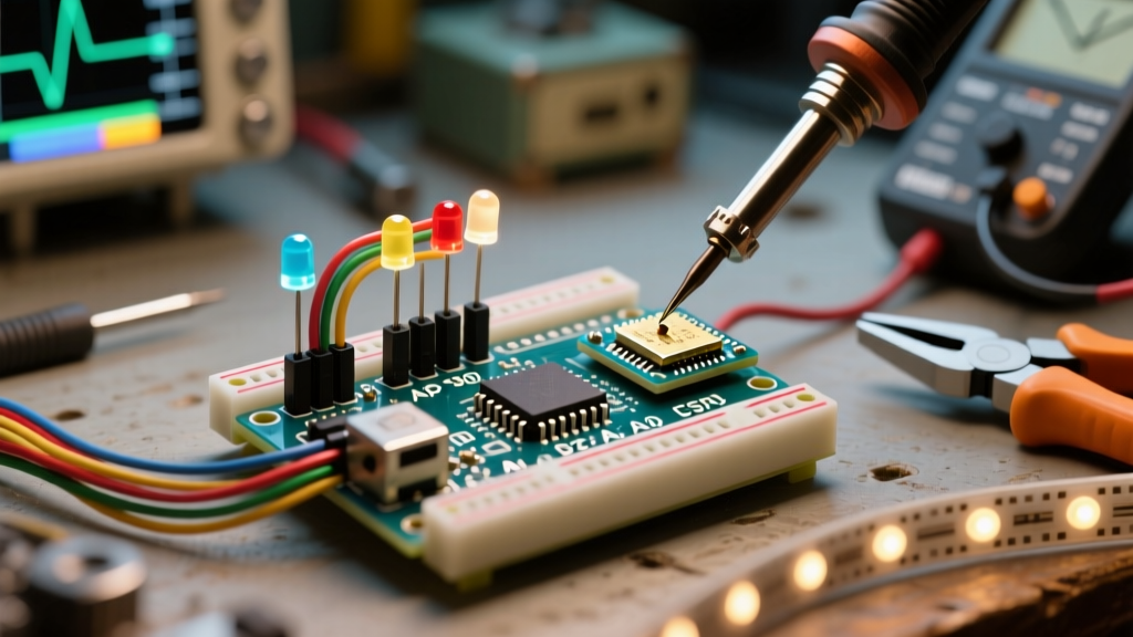
When building a custom lighting rig or interactive display, a standard LED Arduino RGB setup usually falls into one of two categories: analog 5mm through-hole components or addressable digital strips (like the WS2812B). While the Arduino analogWrite Reference makes fading colors seem trivial in code, the physical layer is fraught with edge cases. Mismatched logic levels, inadequate current sourcing, and incorrect common-pin wiring account for over 80% of all RGB troubleshooting tickets in maker forums.
This guide bypasses basic tutorials and dives straight into the electrical and architectural failures that cause flickering, color shifting, and dead pixels in 2026's modern microcontroller ecosystem, including the ARM-based Arduino Uno R4 Minima and legacy AVR boards.
Analog 5mm RGB LEDs: The Common Pin Trap
The most frequent hardware mistake with standard 5mm RGB LEDs is misidentifying the common pin and failing to calculate channel-specific current-limiting resistors. Unlike single-color LEDs, an RGB LED contains three distinct semiconductor dies inside one epoxy housing. They are manufactured in two distinct configurations:
- Common Cathode (CC): The longest leg is ground (GND). The three shorter legs require a HIGH signal (5V) through a resistor to illuminate.
- Common Anode (CA): The longest leg is voltage (5V). The three shorter legs must be pulled LOW (GND) by the Arduino pins to complete the circuit.
Calculating Exact Current-Limiting Resistors
A pervasive myth is that you can use a single 220Ω resistor for all three color channels. This results in severe color imbalance because the forward voltage ($V_f$) of the red die is fundamentally different from the green and blue dies. If you are driving a standard Kingbright WP154A4SUREQBFZGW (Common Cathode) at a safe 20mA per channel from a 5V Arduino Uno R4:
- Red Channel ($V_f \approx 2.0V$): $R = (5V - 2.0V) / 0.02A = 150\Omega$. Use a standard 150Ω resistor.
- Green Channel ($V_f \approx 3.2V$): $R = (5V - 3.2V) / 0.02A = 90\Omega$. Use a standard 100Ω resistor.
- Blue Channel ($V_f \approx 3.2V$): $R = (5V - 3.2V) / 0.02A = 90\Omega$. Use a standard 100Ω resistor.
Expert Warning: Never wire the three cathodes together and share a single resistor to ground. As the PWM duty cycle changes across the three pins, the current draw will dynamically shift, causing the colors to cross-talk and the white balance to collapse entirely.
Addressable RGB Strips: WS2812B and NeoPixel Nightmares
Addressable LEDs integrate a driver IC (like the WS2812B) directly into the 5050 SMD package. While they save I/O pins, they introduce strict timing and power delivery requirements. According to the Adafruit NeoPixel Überguide, ignoring power injection rules will lead to brownouts and corrupted data streams.
The Power Injection Rule of 50
Every WS2812B pixel draws exactly 60mA when displaying full-brightness white (all three internal dies at 100%). A standard 1-meter strip with 60 LEDs will pull 3.6 Amps. The Arduino's onboard 5V regulator or USB-C VBUS line is typically limited to 500mA–800mA. Attempting to power more than 8 pixels directly from the Arduino's 5V pin will trigger the board's polyfuse, cause the microcontroller to brownout and reset, or permanently damage the PCB traces.
The Fix: Use a dedicated 5V 10A switching power supply (approx. $18 on Amazon in 2026). Inject power directly into the strip's VCC and GND pads at the start of the strip, and repeat the injection every 50 pixels to prevent voltage sag across the thin copper FPCB traces.
Logic Level Shifting: The 3.3V vs 5V Data Line Failure
The WS2812B data sheet specifies that a logic HIGH on the DIN pin must be at least $0.7 \times V_{DD}$. If your strip is powered by 5V, the data signal must reach at least 3.5V to be reliably read.
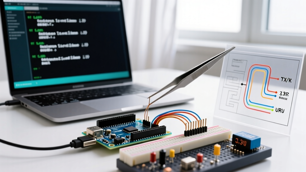
If you are using a 5V AVR board (like the classic Uno R3), this is fine. However, if you have migrated to a 3.3V board (like the Arduino Nano 33 IoT, ESP32, or Raspberry Pi Pico), your 3.3V HIGH signal will fall into the WS2812B's "undefined" logic zone. This manifests as the first LED flickering wildly while the rest of the strip remains dead.
The Fix: Insert a 74AHCT125 level shifter IC between the microcontroller's data pin and the strip's DIN. Alternatively, power the first WS2812B pixel via a 3.3V source (if it supports it) to act as a sacrificial level-shifter, though this is less reliable than a dedicated logic IC.
Diagnostic Matrix: Symptom to Solution
Use this matrix to rapidly isolate your specific LED Arduino RGB failure mode without rewriting your entire sketch.
| Observed Symptom | Probable Root Cause | Hardware Fix | Software / Code Fix |
|---|---|---|---|
| Colors are inverted (e.g., commanding Red yields Cyan) | Using Common Anode LED with Common Cathode code logic | Swap VCC/GND on the common pin | Invert PWM values: analogWrite(pin, 255 - val) |
| First addressable pixel flickers; rest are dead | 3.3V logic level failing to trigger 5V DIN threshold | Add 74AHCT125 level shifter on data line | N/A (Hardware timing issue) |
| Strip turns pink/orange instead of pure white | Voltage sag over long FPCB copper traces | Inject 5V/GND at both ends and every 50 pixels | Limit global brightness to 50% in code |
| RGB fading is jerky or steps visibly | PWM frequency too low or timer conflict | N/A | Use hardware timers or switch to 12-bit PWM on Uno R4 |
Software & PWM Debugging: Beyond analogWrite()
When driving analog RGB LEDs, the FastLED API Documentation and standard Arduino libraries handle the heavy lifting for addressable strips, but analog PWM requires manual tuning. On legacy 8-bit AVR boards, analogWrite() operates at a fixed frequency of ~490Hz (or ~980Hz on pins 5 and 6). This can cause visible flickering on camera or when combined with certain motor drivers that share Timer0.
If you are using the modern Arduino Uno R4 Minima (powered by the 32-bit Renesas RA4M1 ARM Cortex-M4), you have access to 12-bit PWM resolution via the analogWriteResolution(12) function. This expands your color depth from 255 steps to 4095 steps per channel, eliminating the "stepping" effect visible in the lower 10% of the duty cycle during slow fades.
The 400Ω Data Line Resistor Rule
For addressable RGB setups, always place a 300Ω to 500Ω resistor directly on the data wire, as close to the first LED's DIN pad as possible. This is not for current limiting; it is to dampen high-frequency signal reflections and protect the first LED's internal logic gate from voltage spikes caused by capacitive coupling in long wires. Furthermore, place a 1000µF electrolytic capacitor across the main VCC and GND power rails to absorb the initial current surge when the strip turns on.
FAQ: Quick Fixes for Stubborn RGB Setups
Why does my RGB LED glow faintly when it should be completely off?
This is known as "PWM leakage" or ghosting. It usually happens when using a Common Anode LED and the Arduino pin is set to INPUT instead of OUTPUT in the setup() function, or when the microcontroller's internal pull-up resistors are accidentally enabled. Ensure you explicitly call pinMode(pin, OUTPUT) and write the correct OFF state (HIGH for Common Anode, LOW for Common Cathode).
Can I power a 12V RGB LED strip directly from the Arduino?
No. Standard 12V analog RGB strips (like 5050 SMD strips sold in hardware stores) require a 12V source and draw significant current. You must use three N-channel MOSFETs (like the IRLZ44N) to switch the 12V ground paths, using the Arduino's 5V PWM pins to drive the MOSFET gates via a 100Ω gate resistor.