
The Workflow Shift: Why Move to an Arduino in Breadboard Setups?
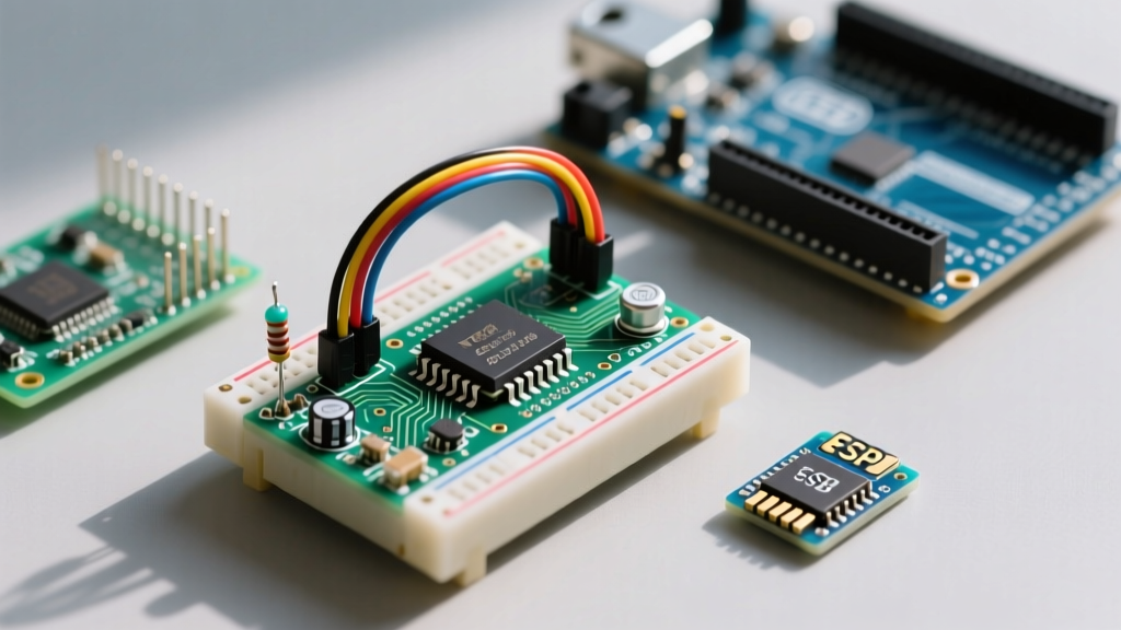
For many makers and embedded engineers, the Arduino Uno is the undisputed starting point for electronics prototyping. However, as projects scale from a single sensor test to a multi-node IoT mesh or a complex robotics rig, tying up a $28 development board for every sub-circuit becomes a massive bottleneck. Transitioning to an arduino in breadboard workflow—specifically using a bare ATmega328P-PU microcontroller—optimizes your bench space, slashes component costs, and forces a deeper understanding of hardware-level initialization.
By stripping away the onboard USB-to-Serial bridge, voltage regulators, and status LEDs, you reduce the node cost to under $4.00 (based on 2026 component pricing). This guide details a professional, repeatable workflow for bootloading, wiring, and uploading code to a standalone ATmega328P on a solderless breadboard, ensuring your prototyping phase is as frictionless as possible.
Bill of Materials: The Minimalist Node
Before initiating the workflow, gather the following components. Sourcing the DIP-28 package (ATmega328P-PU) is critical, as the surface-mount variants (AU/MU) require adapter boards that defeat the purpose of direct breadboard insertion.
| Component | Specification | Est. 2026 Price | Workflow Purpose |
|---|---|---|---|
| Microcontroller | ATmega328P-PU (DIP-28) | $3.20 | Core logic and processing |
| Clock Source | 16 MHz Quartz Crystal (HC-49S) | $0.45 | External timing reference |
| Load Capacitors | 22 pF Ceramic (x2) | $0.10 | Crystal oscillation stability |
| Decoupling Caps | 100 nF (0.1 µF) Ceramic (x2) | $0.10 | High-frequency noise filtering |
| Pull-up Resistor | 10 kΩ (1/4W) | $0.05 | RESET pin stabilization |
| USB-Serial Adapter | CH340C or FT232RL Module (USB-C) | $2.50 | UART bridging for code upload |
Phase 1: Burning the Bootloader via ISP
A bare ATmega328P chip fresh from Microchip does not contain the Arduino Optiboot bootloader, nor is it configured to use an external 16 MHz crystal by default. To integrate it into the standard Arduino IDE ecosystem, you must burn the bootloader using an In-System Programmer (ISP).
Hardware ISP vs. Arduino-as-ISP
While you can use a spare Arduino Uno as an ISP, dedicated hardware programmers like the USBasp v2.0 or the Pololu AVR Programmer v2 drastically reduce connection errors and support 3.3V/5V logic switching natively. Connect the ISP header to the ATmega328P SPI pins as follows:
- MOSI: Pin 17 (PB3)
- MISO: Pin 18 (PB4)
- SCK: Pin 19 (PB5)
- RESET: Pin 1 (PC6)
- VCC/GND: Pins 7, 20 (VCC) and 8, 22 (GND)
In the Arduino IDE, navigate to Tools > Board and select Arduino Uno. Under Tools > Programmer, select your specific ISP device. Finally, click Burn Bootloader. The IDE will set the correct fuse bits (Low: 0xFF, High: 0xDE, Extended: 0xFD) and flash the Optiboot hex file. For deeper architectural reference, consult the Microchip ATmega328P Product Page to verify memory segmentation and fuse lock behaviors.
Phase 2: Minimalist Wiring and Decoupling
Once bootloaded, disconnect the ISP programmer. The chip is now ready to operate as a standalone Arduino node. However, the most common point of failure in an arduino in breadboard workflow is inadequate power decoupling.
Engineering Pro-Tip: The ATmega328P features separate power domains for the digital core (VCC) and the analog-to-digital converter (AVCC). You must place a 100 nF ceramic decoupling capacitor as physically close to the chip legs as possible across pins 7 & 8 (VCC/GND) AND pins 20 & 22 (AVCC/GND). Failure to decouple AVCC will result in erratic analogRead() values and random brownout resets when digital pins switch states.
Wire the 16 MHz crystal between pins 9 (PB6) and 10 (PB7). Connect the 22 pF load capacitors from each crystal leg to the ground rail. Finally, install the 10 kΩ pull-up resistor between Pin 1 (RESET) and the 5V rail to prevent floating noise from triggering unintended resets. The Arduino Official Breadboard Documentation provides excellent visual schematics for this exact minimal configuration.
Phase 3: Optimizing the Upload Workflow
Uploading sketches to a breadboarded chip requires a USB-to-Serial adapter. Modern workflows favor USB-C equipped CH340C or FT232RL breakout boards. Connect the adapter's TX to the ATmega328P RX (Pin 2), and RX to TX (Pin 3).
The Auto-Reset DTR Trick
Manually pressing a reset button on a breadboard exactly when the IDE finishes compiling is a frustrating, error-prone process. To automate this, wire a 100 nF capacitor in series between the adapter's DTR (Data Terminal Ready) pin and the ATmega328P's RESET pin. When the IDE initiates an upload, the DTR line drops low, and the capacitor translates this DC voltage drop into a brief negative pulse on the RESET pin, perfectly timing the bootloader entry. This single addition transforms a clunky manual process into a seamless, one-click workflow.
Advanced Workflow: Bypassing the Crystal for 8MHz Internal Operation
If your project does not require precise UART baud rates or high-speed SPI communication, you can eliminate the 16 MHz crystal and its two load capacitors entirely. The ATmega328P features an internal 8 MHz RC oscillator.
To utilize this, you must burn a different bootloader configuration. Using your ISP programmer, select Arduino Pro or Pro Mini (3.3V, 8 MHz) from the boards menu and burn the bootloader. This sets the Low Fuse to 0xE2, enabling the internal oscillator. This optimization saves three components, reduces breadboard clutter, and lowers the minimum operating voltage to 2.7V—ideal for battery-powered sensor nodes.
Common Failure Modes and Edge Cases
Even with a meticulous workflow, breadboard environments introduce parasitic capacitance and loose connections. Here is how to troubleshoot the most frequent roadblocks:
- avrdude: stk500_getsync() attempt 1 of 10: This generic sync error usually means the IDE cannot communicate with the bootloader. Verify that RX/TX lines are crossed (TX to RX, RX to TX). If using the DTR auto-reset trick, ensure the 100 nF capacitor is not shorted or installed backwards (though ceramic caps are non-polarized, physical breadboard damage can cause internal shorts).
- Random Brownouts During Motor Switching: Breadboard power rails have high inductance. If your circuit drives relays or motors, the 100 nF decoupling caps are insufficient. Add a 10 µF to 47 µF electrolytic bulk capacitor across the main power rails to supply transient current demands.
- Bootloader Bricking via SPI: If you accidentally set the fuse bits to require a clock source that isn't present (e.g., disabling the internal oscillator without a crystal attached), the chip will appear "dead" to your ISP programmer. You will need to provide a temporary 16 MHz clock signal to the XTAL1 pin via a secondary Arduino or a dedicated clock generator to recover the chip and reset the fuses. For recovery procedures, review the SparkFun Bootloader Tutorial.
- ADC Noise on Breadboards: Solderless breadboards suffer from crosstalk. If you are reading high-impedance sensors (like passive thermistors or photoresistors), keep analog traces away from digital switching lines (like I2C or SPI clocks) on the breadboard to prevent capacitive coupling.
Final Workflow Considerations
Migrating to an arduino in breadboard topology is a rite of passage that bridges the gap between hobbyist tinkering and professional embedded design. By mastering the ISP bootloading process, implementing proper hardware decoupling, and utilizing the DTR auto-reset circuit, you create a rapid-prototyping environment that is both cost-effective and highly reliable. Once your breadboard circuit is validated, the transition to a soldered perfboard or custom PCB becomes a straightforward exercise in routing, rather than a debugging nightmare.