
The Essential Quick Reference for Rotary Encoders
Integrating a rotary encoder for Arduino projects is the gold standard for precision user interfaces, motor speed control, and robotics navigation. Unlike potentiometers, which are limited by their physical rotation arc and suffer from wiper noise, incremental rotary encoders offer infinite rotation and digital quadrature outputs. However, makers frequently encounter skipped steps, ghost inputs, and backward counting due to improper interrupt handling or missing hardware debouncing.
This FAQ and quick reference guide cuts through the noise. We provide exact wiring diagrams, RC filter calculations, and software architecture advice for modern 2026 microcontrollers, including the Arduino Uno R4 Minima, Nano ESP32, and classic ATmega328P boards.
Quick Reference: Rotary Encoder Modules Compared
Choosing the right hardware prevents 90% of software headaches. Below is a comparison of the most common encoder modules used in the maker community, with updated 2026 market pricing.
| Module / Model | Interface Type | Avg. Price (2026) | Detents / Pulses | Pull-ups Included? | Best Use Case |
|---|---|---|---|---|---|
| KY-040 (Generic EC11) | Quadrature (A/B) | $1.20 - $1.80 | 20 Detents / 20 PPR | Yes (10kΩ on PCB) | Budget UI menus, basic volume knobs |
| Bourns PEC11R-4215F | Quadrature (A/B) | $3.50 - $4.20 | 15 Detents / 15 PPR | No (Bare component) | High-reliability industrial prototypes |
| SparkFun RGB Encoder (COM-15141) | Quadrature + PWM | $12.95 | 20 Detents / 20 PPR | No (Breakout board) | Smart home dashboards, aesthetic UI |
| Adafruit I2C Rotary Encoder (4991) | I2C (Seesaw chip) | $9.50 | 20 Detents | N/A (Digital I2C) | Projects with pin-starved MCUs (e.g., ATtiny) |
Frequently Asked Questions: Hardware & Wiring
How do I wire a standard KY-040 module to an Arduino Uno R4?
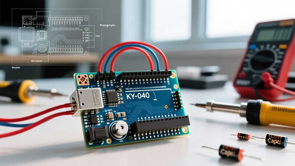
The KY-040 breakout board features five pins: GND, + (VCC), SW (Switch), DT (Data), and CLK (Clock). For optimal performance on an Uno R4 Minima or classic Uno R3, wire the module as follows:
- GND: Connect to Arduino GND.
- + (VCC): Connect to 5V (or 3.3V if using a Nano ESP32).
- CLK (Clock): Connect to Pin 2 (Hardware Interrupt 0).
- DT (Data): Connect to Pin 3 (Hardware Interrupt 1).
- SW (Switch): Connect to Pin 4 (Configure as
INPUT_PULLUPin software).
Crucial Note for ESP32 Users: If you are using a Nano ESP32 or standard ESP32-DevKitC, almost all GPIO pins support interrupts. However, avoid using GPIO 0, 2, and 12 for encoders if you are also utilizing the onboard SPI/I2C buses or strapping pins for boot modes.
Do I need external pull-up resistors?
If you are using a bare Bourns PEC11R or SparkFun breakout, yes. Quadrature encoders use open-collector or mechanical switches that float when open. You must use 10kΩ resistors pulling both the A (CLK) and B (DT) lines to VCC. The cheap KY-040 modules already include 10kΩ SMD pull-ups on the PCB, so you can rely on those, provided you are operating at 5V.
Frequently Asked Questions: Software & Interrupts
Why is my encoder skipping counts or reading backward?
This is the most common issue when using a rotary encoder for Arduino projects. It happens because mechanical encoders output a quadrature signal (Gray code). The CLK and DT pins transition through four distinct states per detent. If you use digitalRead() inside the main loop() (polling), the microcontroller will inevitably miss the microsecond-long state changes while executing other code, like updating an I2C OLED display.
The Fix: You must use hardware interrupts. By attaching an Interrupt Service Routine (ISR) to the CLK pin's CHANGE edge, the MCU pauses the main loop the exact microsecond the encoder moves, reads the DT pin to determine direction, and updates a volatile counter variable.
What is the best software library for decoding encoders in 2026?
Stop writing custom state-machine ISRs from scratch unless you are optimizing for extreme memory constraints. The industry standard is Paul Stoffregen's Encoder Library. It handles the complex 4x resolution quadrature decoding, manages bounce implicitly through state validation, and supports multiple encoders simultaneously across different architectures (AVR, ARM Cortex, ESP32, RP2040).
Install it via the Arduino IDE Library Manager by searching for Encoder by Paul Stoffregen. Initialize it using the hardware interrupt pins:
#include <Encoder.h>
Encoder myEnc(2, 3); // Pins 2 and 3 on Uno

void loop() {
  long newPosition = myEnc.read();
  if (newPosition != oldPosition) {
    oldPosition = newPosition;
    Serial.println(newPosition);
  }
}
Signal Integrity: The Hardware Debounce Fix
Even with excellent software libraries, cheap mechanical encoders like the KY-040 generate massive contact bounce—sometimes ringing for up to 5 milliseconds. This causes the ISR to fire dozens of times per detent, resulting in erratic jumping values.
Pro-Tip: The RC Low-Pass Filter
Before adding software delays (which block your main loop), add a hardware RC filter. Solder a 100nF (0.1µF) ceramic capacitor between the CLK pin and GND, and another between the DT pin and GND. Combined with the 10kΩ pull-up resistor, this creates a low-pass filter with a time constant of τ = RC = 1ms. This smoothly filters out high-frequency mechanical bounce without delaying the actual detent signal. For a deep dive on MCU interrupt handling, refer to the official Arduino Interrupt Documentation.
Edge Case Troubleshooting Matrix
When your rotary encoder for Arduino setup misbehaves, use this diagnostic matrix to isolate the root cause quickly.
| Symptom | Root Cause | Hardware Fix | Software Fix |
|---|---|---|---|
| Counts increase by 2 or 3 per single detent click. | Software is reading both Rising and Falling edges incorrectly, or switch bounce is triggering multiple ISRs. | Add 100nF capacitors from CLK/DT to GND. | Use Stoffregen's Encoder library; avoid attachInterrupt with RISING only. |
| Encoder works alone, but freezes when updating I2C OLED. | Interrupt starvation or I2C bus capacitance causing slow rise times on shared ground planes. | Ensure OLED and Encoder do not share long, unshielded ground wires. Add 4.7kΩ I2C pull-ups. | Keep ISRs under 5 microseconds. Never use Serial.print() or Wire inside an ISR. |
| Direction reverses randomly or reads backward. | CLK and DT wires are swapped, or the encoder lacks a common ground with the MCU. | Swap the CLK and DT wires at the breadboard. Verify GND continuity. | Multiply the position delta by -1 in code (lazy fix, not recommended). |
| Push-button (SW) triggers ghost inputs when rotating. | Crosstalk between the switch line and the quadrature lines due to capacitive coupling on cheap breadboards. | Move the SW wire away from CLK/DT wires. Enable internal pull-up (INPUT_PULLUP). |
Implement a 50ms software debounce timer specifically for the SW pin state. |
Summary Checklist for Production-Ready Encoder Integration
- Select the right hardware: Upgrade to Bourns or Alps mechanical encoders for final products; reserve KY-040 for breadboard prototyping.
- Wire to dedicated interrupt pins: Pin 2 and 3 on AVR; any GPIO on ESP32/RP2040.
- Implement hardware filtering: 10kΩ pull-ups and 100nF decoupling capacitors are mandatory for clean signals.
- Use proven libraries: Leverage hardware-optimized quadrature decoding libraries rather than reinventing the state machine.
- Keep ISRs lean: Set a
volatile boolflag inside the ISR, and handle the heavy logic (like updating an LCD menu or writing to EEPROM) inside the mainloop().
For further reading on integrating rotary inputs with advanced RGB feedback, check out the SparkFun RGB Encoder Hookup Guide, which details PWM multiplexing techniques alongside quadrature decoding.