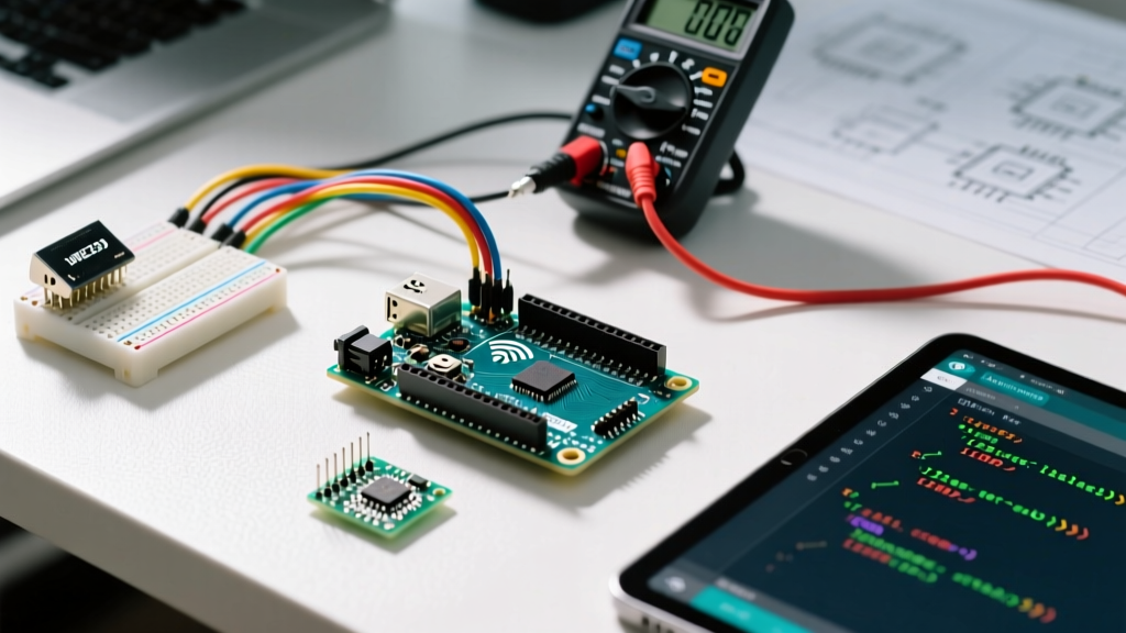

Why the Arduino Uno R4 WiFi is the Modern Maker Standard
If you are searching for exactly how to use the Arduino in a modern prototyping environment, you must look past the legacy Uno R3. As of 2026, the Arduino Uno R4 WiFi is the definitive entry point for microcontroller development. Priced at roughly $27.50, it replaces the aging 8-bit ATmega328P with a 32-bit Renesas RA4M1 Arm Cortex-M4 running at 48 MHz, paired with an ESP32-S3 coprocessor for native WiFi and Bluetooth LE connectivity.
This tutorial will walk you through configuring the Arduino IDE 2.3.x, wiring an I2C environmental sensor, and writing your first robust sketch. We will bypass generic 'blink' tutorials and immediately tackle real-world hardware integration using the Bosch BME280 sensor.
Hardware Bill of Materials (BOM)
Before writing code, ensure you have the correct hardware. Using substandard components is the primary cause of beginner frustration.
| Component | Specific Model / Spec | Approx. Cost (2026) | Notes |
|---|---|---|---|
| Microcontroller | Arduino Uno R4 WiFi (ABX00087) | $27.50 | Ensure it is the official 'WiFi' variant, not the 'Minima'. |
| Sensor | BME280 Breakout (Adafruit 2652) | $9.95 | Measures temp, humidity, and barometric pressure. |
| Cable | USB-C to USB-A Data Cable | $6.00 | Critical: Must have 4 internal wires (data + power). |
| Wiring | 22 AWG Solid Core Hookup Wire | $8.00 | Stranded wire will fray in breadboards; use solid core. |
| Prototyping | Half-Size Solderless Breadboard | $4.50 | 400 tie-points is sufficient for this circuit. |
Step 1: Configuring Arduino IDE 2.3 for the Renesas Core
The Uno R4 requires a specific board support package because its architecture differs entirely from older AVR boards. According to the Arduino IDE Board Manager documentation, you must install the Renesas core to compile code for the RA4M1 chip.
- Download and install the latest Arduino IDE 2.3.x from the official website.
- Open the IDE and navigate to Tools > Board > Boards Manager.
- Search for
Arduino UNO R4 Boardsand click Install. This downloads the Renesas compiler toolchain and the ESP32-S3 network bridge firmware. - Connect your Uno R4 WiFi to your PC via the USB-C data cable.
- Navigate to Tools > Port and select the COM port (Windows) or
/dev/cu.usbmodem...(macOS) labeled 'Arduino Uno R4 WiFi'.
Expert Warning: If your board does not appear in the Port menu, you are almost certainly using a 'charge-only' USB-C cable. These cables lack the D+ and D- data lines. Swap to a verified data cable before attempting driver troubleshooting.
Step 2: Wiring the BME280 Sensor via I2C
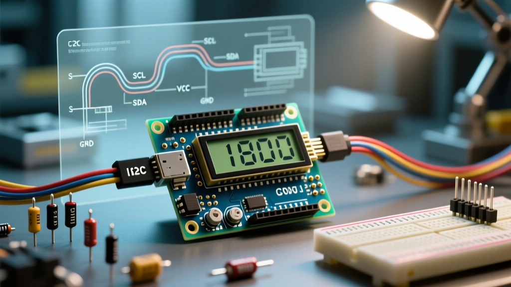
The BME280 communicates using the I2C (Inter-Integrated Circuit) protocol. On the Uno R4, the I2C pins are physically located at A4 (SDA) and A5 (SCL), maintaining backward compatibility with R3 shields, though internally they route to the Renesas chip's dedicated I2C peripheral.
Refer to the Adafruit BME280 wiring guide for the following physical connections:
- VIN / VCC: Connect to the Uno R4
5Vpin (The Adafruit breakout has an onboard 3.3V LDO regulator). - GND: Connect to any Uno R4
GNDpin. - SCL: Connect to Uno R4 pin
A5. - SDA: Connect to Uno R4 pin
A4.
Note: The Adafruit breakout includes 10kΩ pull-up resistors on the SDA and SCL lines. If you are using a generic $3 clone module from overseas marketplaces, you may need to add external 4.7kΩ pull-up resistors between VCC and the I2C data lines to prevent bus capacitance errors.
Step 3: Writing the Environmental Monitoring Sketch
To interact with the sensor, we utilize the Wire.h library (for I2C communication) and the Adafruit BME280 library. Install the latter via Sketch > Include Library > Manage Libraries by searching for 'Adafruit BME280'.
Upload the following code to your board. This sketch initializes the sensor at its default I2C address (0x77 or 0x76 depending on the jumper pad) and outputs formatted data to the Serial Monitor.
#include <Wire.h>
#include <Adafruit_Sensor.h>
#include <Adafruit_BME280.h>

#define SEALEVELPRESSURE_HPA (1013.25)

Adafruit_BME280 bme;
unsigned long delayTime;

void setup() {
  Serial.begin(115200);
  // Wait for serial port to connect. Native USB boards need this delay.
  while (!Serial) { delay(10); }

  Serial.println(F("BME280 Initialization Sequence..."));

  // Initialize I2C with default SDA/SCL pins
  if (!bme.begin(0x77, &Wire)) {
    Serial.println(F("Could not find a valid BME280 sensor at 0x77!"));
    Serial.println(F("Check wiring, I2C address, or try 0x76."));
    while (1) { delay(10); } // Halt execution on failure
  }

  Serial.println(F("Sensor initialized successfully."));
  delayTime = 2000; // 2-second polling interval
}

void loop() {
  float tempC = bme.readTemperature();
  float pressureHpa = bme.readPressure() / 100.0F;
  float humidity = bme.readHumidity();

  Serial.print("Temp: "); Serial.print(tempC); Serial.print(" C | ");
  Serial.print("Pressure: "); Serial.print(pressureHpa); Serial.print(" hPa | ");
  Serial.print("Humidity: "); Serial.print(humidity); Serial.println(" %");

  delay(delayTime);
}
Advanced Troubleshooting: Edge Cases and Failure Modes
Even with perfect wiring, microcontroller development involves debugging hardware-software intersections. Here is how to resolve the most common roadblocks when learning how to use the Arduino Uno R4 platform.
1. The 'Upload Stuck at 100%' Error
The Renesas RA4M1 utilizes a different bootloader mechanism than the legacy ATmega328P. If the IDE hangs at 'Uploading...' and eventually times out, the board may have crashed and failed to trigger the auto-reset circuit.
The Fix: Perform a double-tap reset. Quickly press the physical reset button on the Uno R4 twice in succession. The onboard 'L' LED will pulse, indicating the board has entered ROM bootloader mode. Immediately click 'Upload' in the IDE while the LED is pulsing.
2. I2C Bus Lockups and 'NaN' Readings
If your Serial Monitor outputs NaN (Not a Number) for temperature or humidity, the I2C bus has likely locked up due to electrical noise or a missing ground reference.
- Verify Common Ground: Ensure the GND pin on the sensor is tied directly to the GND pin on the Arduino. A floating ground will cause the I2C logic levels to drift.
- Check VCC Stability: Measure the 5V pin on the Uno R4 with a multimeter. If it reads below 4.8V while connected to an unpowered USB hub, the sensor's internal LDO will brown out, corrupting I2C registers.
3. Utilizing the 12x8 LED Matrix for Visual Debugging
One of the most powerful features of the Uno R4 WiFi is the onboard 12x8 red LED matrix. Instead of relying solely on the Serial Monitor, you can map sensor thresholds to visual indicators. By including the Arduino_LED_Matrix.h library, you can render scrolling text or bar graphs representing humidity levels directly on the board without external components. For comprehensive pinout and matrix mapping details, always refer to the official Arduino Uno R4 WiFi documentation.
Next Steps in Your MCU Journey
Mastering how to use the Arduino ecosystem requires moving beyond simple sensor polling. Once your BME280 is reliably outputting data, your next milestone should be leveraging the ESP32-S3 coprocessor to push that telemetry to an MQTT broker or a local Grafana dashboard via WiFi. The Uno R4 WiFi bridges the gap between bare-metal microcontroller programming and IoT network engineering, making it the ultimate sandbox for modern electronics development.